CFG253 Performance Verification & Adjustment Procedures
Page 9 of 19 Procedure #: CP1005 Revision: A
6. SINE WAVE DISTORTION
a. Set-Up:
RANGE 100K
FUNCTION Sine Wave
VOLTS OUT Button Out
FREQ/10 Button Out
FREQ DIAL 1.0
b. Connect MAIN OUTPUT to Distortion Analyzer via coax cable and 50 ohm
terminator.
c. Set the Distortion Analyzer INPUT RANGE to Auto Range, and the FUNCTION
settings to Volts, Auto Range and THD+N.
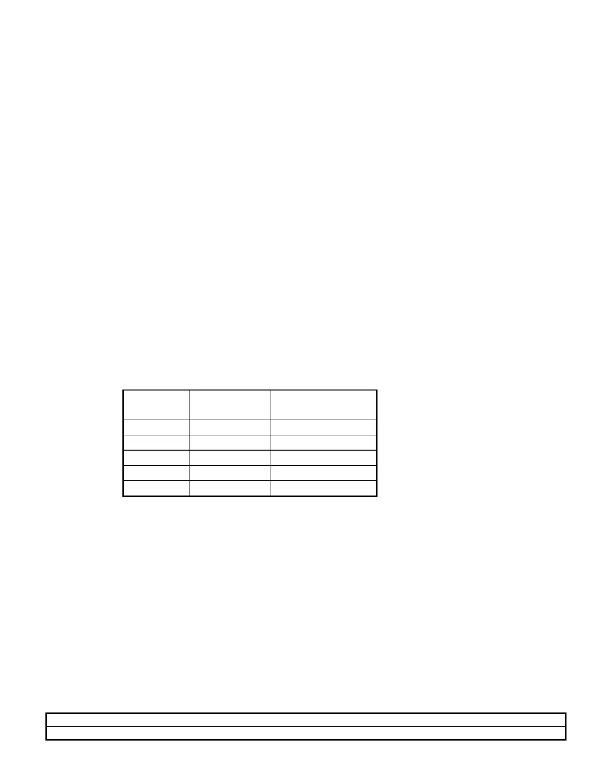
d. CHECK- For less than 1% distortion for the frequencies listed in Table 5:
Table 5
RANGE FREQ DIAL PER CENT
DISTORTION
100K 1.0 < 1 %
10K 1.8 < 1 %
1K 1.8 < 1 %
100 1.8 < 1 %
10 1.0 < 1 %
7. FREQUENCY DIAL ACCURACY
a. Set-Up:
AMPLITUDE CW
RANGE 1K
FUNCTION Triangle
VOLTS OUT Button In
FREQ/10 Button Out
FREQ DIAL 3.0

 Loading...


