PS2520 Series Performance Verification
Handheld and Benchtop Instruments Basic Service
19
7. Press VOLTS
to increase the power supply output voltage until the error
message “Err - 013” appears on the readouts. Verify that the readouts
indicate between 4.3 and 5.7 V prior to error message activation.
8. Press SHIFT
→ OVP RESET.
9. Reset the output voltage to 4 V.
10. Repeat steps 6 through 9 above as necessary to determine the exact voltage.
11. Press OUTPUT ON/OFF. Verify that the “OUT” indicator turns off.
Complete the following procedures to verify constant voltage load accuracy.
Outputs 1 and 2. Use the following steps to check the OUTPUT 1 and
OUTPUT 2 accuracy.
1. Press SHIFT
→ OUT 1; verify that the “1” indicator lights up on the display.
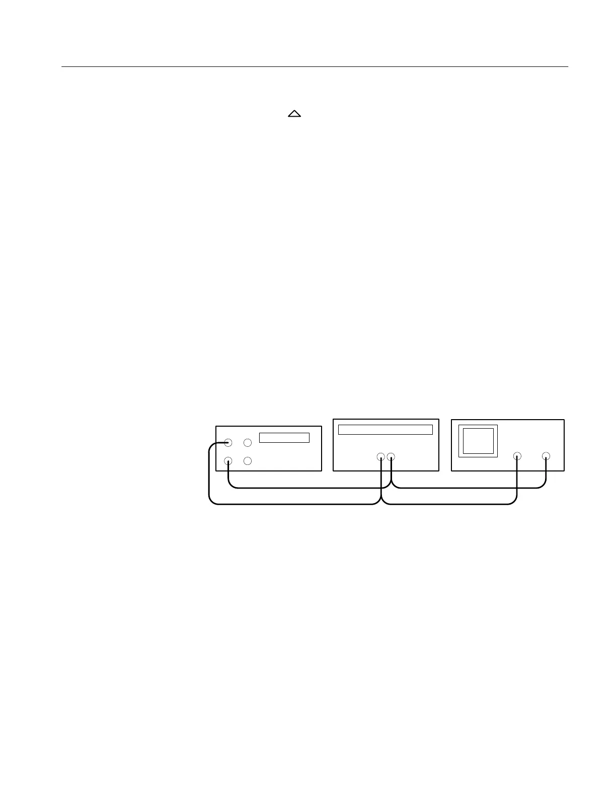
2. Ensure that the power supply output is disabled. Connect the DMM and
electronic load to the front panel OUTPUT 1 terminals. See Figure 2 for
details.
+
–
Power supply
Electronic load
–
+
Digital multimeter
+–
10 A
COM
Figure 2: Constant Voltage Load Test Setup
3. Set the DMM to measure 40 VDC.
4. Set up the power supply as follows:
VOLTS SET 36 V
CURRENT SET 1.55 A
OVP SET 38.5 V
5. Press OUTPUT ON/OFF. Verify that the “OUT” indicator lights up on the
display.
6. Enable the electronic load. Adjust the load until the power supply
CURRENT (A) readout indicates 1.500 A.
Constant Voltage
Load Accuracy
 Loading...


