DCM330 Adjustment Procedures
16
Handheld and Benchtop Instruments Basic Service
14. Remove the clamp meter from the coil.
15. Reassemble the meter.
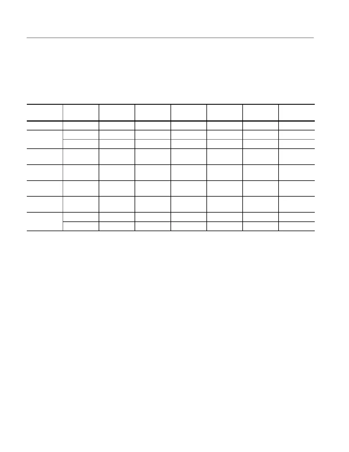
Table 11: Summary of Adjustments
Adjustment
Name
Mode Test Value Frequency
Circuit
Location
Tolerance Display Min. Display Max.
Position Error AC 380 A 50 Hz VR1 <5 counts 0 count 5 counts
D
Zero DC VR2
1
±0.5 –00.5 00.5
DC VR3 ±0.1 –00.1 +00.1
DC 400 A
Range
DC 200.0 A VR5 ±0.5 201.2 201.8
DC 1000 A
Range
DC 400 A VR6 ±1 399 401
AC 400 A
Range
AC 390.0 A 400 Hz VR8 ±0.1 395.5 396.5
AC 1000 A
Range
AC 400 A 400 Hz VR7 ±1 399 401
Peak Hold AC VR9
2
00.0 00.0
AC 200.0 A 120 Hz VR10
2
±0.1 199.9 200.1
1
Auto Zero points shorted.
2
Peak Hold points shorted.
 Loading...


