TM 11-6625-2980-14
Risetime Measurements In Linear Systems
Consider the rise and falltime of associated
equipment when measuring the rise or falltime of a
linear device. If the risetime of the device under test is
at least ten times slower than the combined risetimes of
the PG 508, the monitoring oscilloscope, and associated
cables, the error introduced will not exceed 1%, and
usually may be ignored. If the rise or falltime of the test
device is less than ten times slower than the combined
risetimes of the testing systems, determine the actual
risetime of the device under test by using the following
formula:
R,= VR
21
+ R
2
2
+R2 3 .......
R, equals the overall rise or falltime of the entire
measurement system and R1, R2, R3, etc., are the
risetimes or falltimes of the individual components
comprising the system.
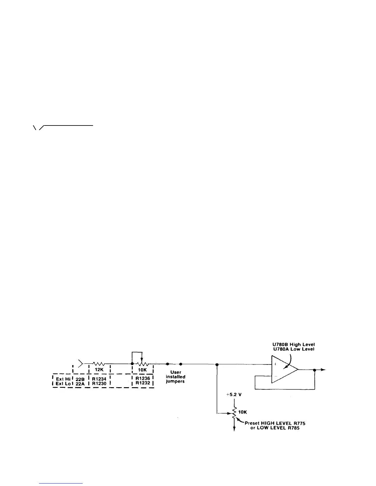
External Voltage Control
The high and low level output voltages can be
controlled externally through pins 22B and A at the rear
interface connector. Fig. 1-4 shows the equivalent
circuit.
Connections must be made from pad K to pad L and
pad M to pad N located as shown on the adjustment
location illustration in the fold out pages at the rear of
this manual. Use ordinary hookup wire of the proper
length. Solder the wire to the pads. Also note the
location of the Ext Hi and Ext Lo potentiometers on the
output board.
To use this feature, set the front panel controls as
follows: depress the PRESET button (PRESET), place
the PERIOD switch in the EXT TRIG OR MAN position,
the DURATION in EXT DUR and the NORM
COMPLEMENT switch in the NORM position (out). Use
a screwdriver to center the Ext Hi and the preset HIGH
LEVEL controls. Supply a voltage to the external high
input (pin 22B on the rear interface connector) equal to
the lowest external input voltage desired (maximum 20
V).
Now adjust the front panel preset HIGH LEVEL
control for an OUTPUT voltage equal to the minimum
desired output voltage. It may be necessary to adjust
the preset LOW LEVEL control as the OUTPUT voltage
is limited to 20 V peak to peak open circuit. The high
level OUTPUT voltage is clamped by the low level
OUTPUT voltage if this range is exceeded. Now apply a
voltage equal to the highest external control voltage
desired to the same rear interface connector (pin 22B).
Adjust the Ext Hi potentiometer until the highest desired
output voltage is obtained. It may be necessary to adjust
the preset LOW LEVEL control to obtain the desired
output. The high level OUTPUT voltage cannot go
below the low level OUTPUT voltage due to the level
control voltage clamps. The Ext Hi and the preset HIGH
LEVEL controls interact. It may be necessary to repeat
the above procedure several times until the desired
results are obtained.
Now push the NORM COMPLEMENT switch
(COMPLEMENT). Center the Ext Lo and preset LOW
LEVEL potentiometers. Supply a voltage to pin 22A of
the rear interface connector equal to the lowest external
control voltage desired. Adjust the preset LOW LEVEL
control for an OUTPUT voltage equal to the lowest
OUTPUT voltage desired. Change this voltage to the
highest desired external control voltage. Adjust the Ext
Lo potentiometer for the highest OUTPUT voltage
desired. As these adjustments interact, readjust the
preset LOW LEVEL and the Ext Lo potentiometers for
the desired results. Do not readjust the preset HIGH
LEVEL or the Ext Hi potentiometers. The OUTPUT
voltages now vary linearly and independently with the
external control voltage.
Counted Burst Using the DD 501 Digital Delay Unit
This application permits pre-selecting the number of
output pulses from the PG 508. The event is initiated by
an externally applied signal or pulse, 5 ns or longer. The
time duration of this signal or pulse has no effect on the
output from the PG 508.
Fig . 1-4 . Equivalent circuit of external input for output voltage control .
1-5
 Loading...
