TM 11-6625-298014
BASIC OPERATION
Period and Duration Selection
The period generator operates, in all modes except
EXT TRIG or MAN, at a rate set by the PERIOD range
switch and variable control. The duration of the output
pulse is set by the DURATION range switch and
variable control. When the DURATION control is set for
a time greater than the PERIOD, the CONTROL
ERROR lamp will light. When the DURATION control is
set to the SQ WAVE position, the duration time is
determined internally at approximately 50% of the
period time.
The custom range positions on the PERIOD and
DURATION controls permit user-selected period and
duration times. To determine the approximate capacitor
value for the desired period, multiply the period time in
seconds by 5 X 10
-3.
The result is the value of the
capacitor in Farads. For example, a 50 ms period times
5 X 10⁻³ equals 250 X 10- or 250 HF. This capacitor
must be non-polarized and have at least a 6 V rating.
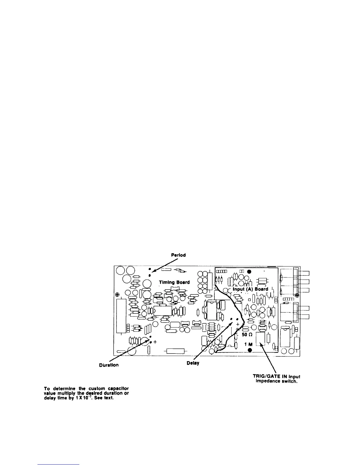
Solder this capacitor in the position shown in Fig. 1-2.
To determine the capacitor value for the duration
time desired, multiply the duration time by 1 X 10
-2.
For
example a 50 ms duration time requires 50 ms times 1
X
10
-2
or a 500pF capacitor. If a polarized capacitor is
used, observe the correct polarity. Use at least a 6 V
rated capacitor. Connect this capacitor as shown in Fig.
1-2.
Duty Factors
Duty factors greater than those specified are obtainable
on several ranges. When the duty factor is increased to
the point that internal circuitry prevents completion of
the pulse waveform, the CONTROL ERROR light will
flash. To further increase the duty factor, switch to the
complement mode. Set the DURATION control for a
pulse width equal to the desired pulse off time and push
the front panel COMPLEMENT (-) pushbutton.
Delayed and Paired Pulse Selection
In the pulse delay mode, the output pulse is delayed
from the +TRIG OUT signal by the DELAY time
selected plus a specified fixed delay. In the PAIRED
mode of operation, the delay controls the time between
the leading edges of the paired pulses. To use this
feature push the DELAY button and trigger the external
device from the +TRIG OUT jack. Set the DELAY
control for the desired delay time from trigger to pulse
leading edge. Use the variable control labeled CAL for
time adjustments between steps or to increase the delay
times beyond the steps.
Fig. 1-2. Locations of period, delay and duration custom timing capacitors and TRIG/GATE IN input
impedance switch. Remove the Input board to gain access to the delay pads.
1-2
 Loading...
