TM 11-6625-2980-14
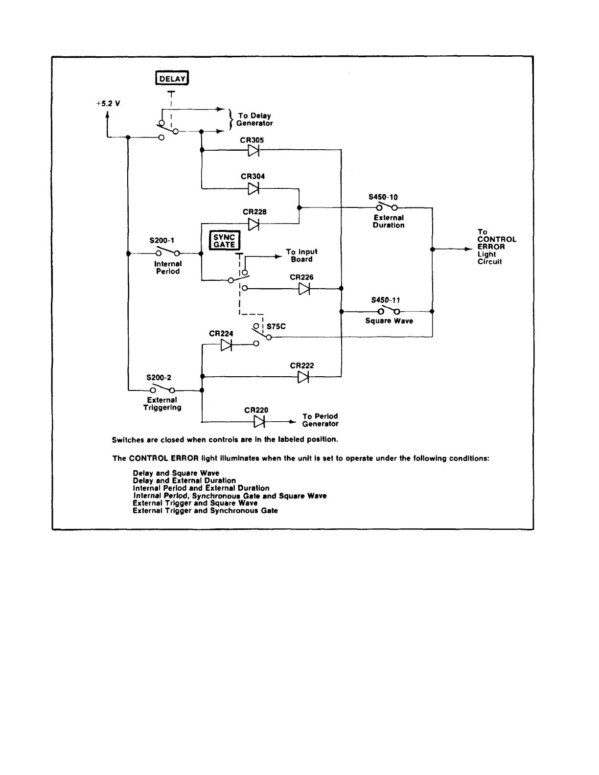
Fig . 2-1 . Simplified schematic for CONTROL ERROR Indicator logic with control settings causing Illumination .
proximately the same amount as the circuitry in the
variable transition time generator. The positive-going
waveform from pin 14 of U740C is fed through pin 6 to
the clock input, pin 6, of flip flop U720A. The negative-
going output from pin 15 is fed to the clock input pin 11,
of flip flop U720B. Flip flop U720A senses the pulse
trailing timing error and U720B, the pulse leading timing
error. If the leading time from the output of the variable
transition time generator is slow enough so that the D
input of U720B has not dropped below approximately
the 50% point, when the waveform at the clock input of
flip flop U720B (waveform driving the transition time
board) goes positive (end of pulse), the high on D input,
pin 10, transfers to the output, pin 15, and the
CONTROL ERROR lamp is lit.
When pin 15, of flip flop U720B goes high, C734
starts to charge through R728. When the voltage at pin
13 of U720B and pin 5 of U720A reaches the high level
(-4.0 V), both flip flops are reset to their initial conditions
and the CONTROL ERROR light goes out. If the trailing
time of the
2-4