Installation Instructions
6 SPG600 & SPG300 Sync Pulse Generators Upgrade Kit
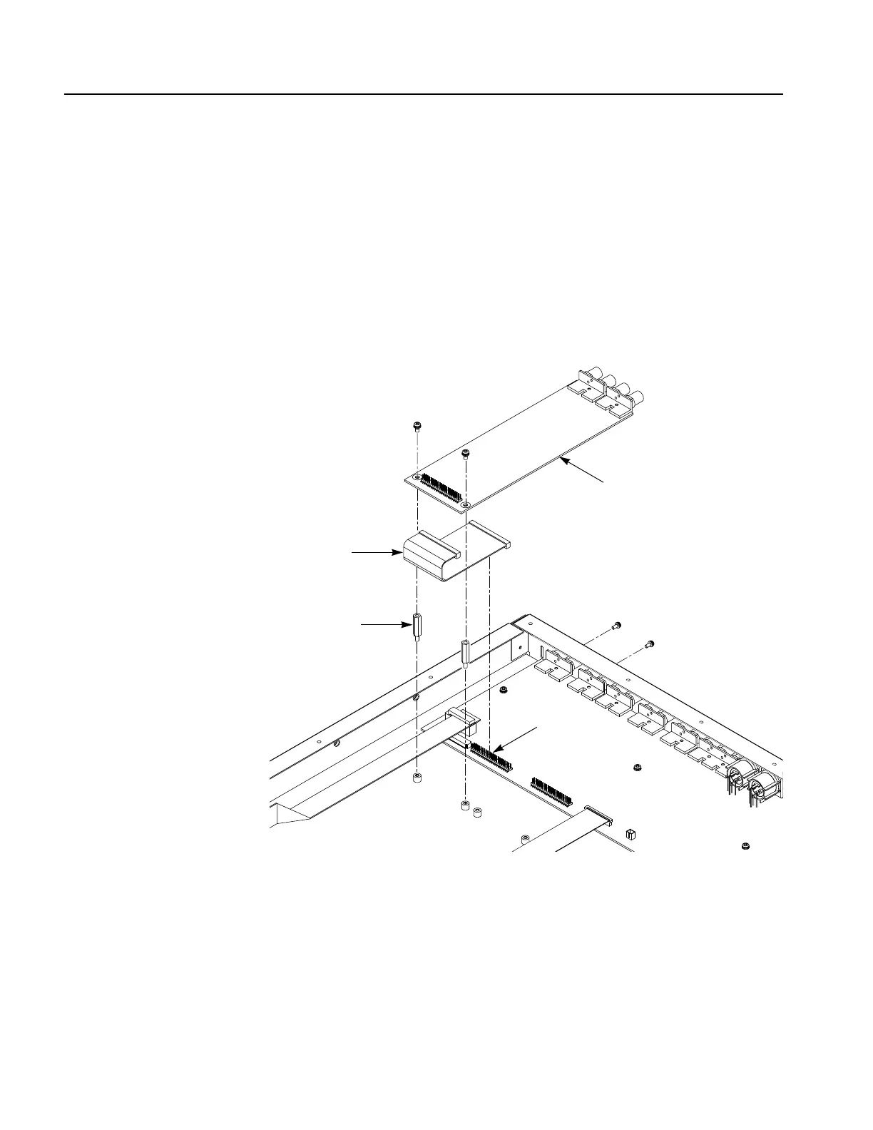
5. Use a 5.5 mm size nut driver to install the two spacer posts to the chassis.
See Figure 2.
6. Connect the one end of the flat cable provided in the kit at J610 on the A10
Main board. See Figure 2.
7. Use a screwdriver with a #1 Phillips tip to install the two screws (M2.6 X 6)
securing the analog video outputs board to the rear panel. See Figure 2.
8. Use a screwdriver with a #2 Phillips tip to install the two screws (M3 X 6)
securing the analog video outputs board to the spacer posts. See Figure 2.
Figure 2: Installing the analog video outputs board
9. Connect the other end of the flat cable to J1 on the analog video output board.
10. Use a screw driver with a #2 Phillips tip to reinstall the top cover to the chassis.
11. Remove the protective backing from the label marked “SPG6UP 02” and apply
it to the right side of the instrument, just under the serial number label.
Flat cable
Spacer post
Analog video outputs board (A30)
J610
A10 Main board
 Loading...