Operatins Basics
Using Autoset
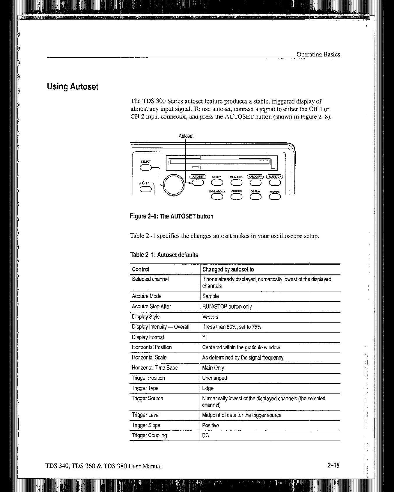
The TDS 300 Series autoset feature produces a stable, triggered display of
almost any input signal. To USC autosct, connect a $@a1 to either the CH 1 or
CH 2 input connector, and press the AUTOSET button
(shown j,n Figure Z-8)
Figure 2-8: The AUTOSET button
Table 24 specifics the changes autoset makes in your oscilloscope setup.
table Z-l: Autoset defaults
Control
Selected channel
Changed by autoset to
If none already displayed, numetically lowesf of the displayed
channels
Acauire Mode
I Sam&
Acquire Stop After
Display Style
Disolav lntensitv - Overall
RUN/STOP button only
vectors
If less than 50%. set to 75%
,, ,
Display Format
Horizontal Position
Yr
Centered within the graticule window
Horizontal Scale
1 As determined by the signal frequency
Horizontal Ime Base 1 Main Only
Triqqer Position 1 Unchanged
TriggerType
Trigger Source Numerically lowest of the displayed channels (the selected
channel)
Triqqer Level 1 Midpoint of data for the triqqer source
Tnsaer Slope I Positive
Triaaer Coudina
I DC
TDS 340, TDS 360 & TDS 380 User Manual
2-15 ;;
I
Artisan Technology Group - Quality Instrumentation ... Guaranteed | (888) 88-SOURCE | www.artisantg.com
 Loading...


