Home
Tektronix
Test Equipment
TDS 700A
Tektronix TDS 700A User Manual
4
of 1
of 1 rating
303 pages
Give review
Manual
Specs
To Next Page
To Next Page
To Previous Page
To Previous Page
Loading...
Saving W
aveforms and Setups
TDS 500B, TDS 600B, & TDS 700A User Manual
3–137
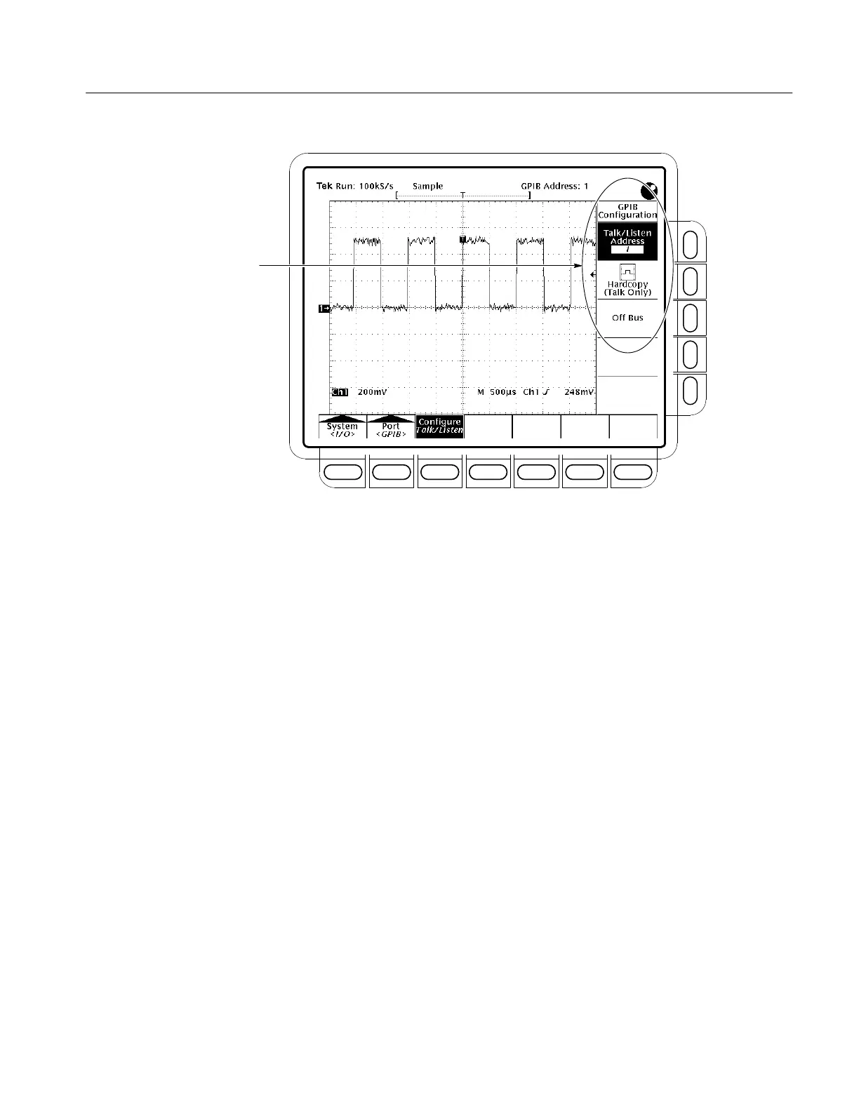
GPIB Configuration Menu
Figure 3–78: Utility Menu
See
Printing a Har
dcopy
,
on page 3–125.
See the
TDS Pr
ogrammer Manual
, T
ektronix part number 070-9385-XX.
T
o Find More Information
192
194
Table of Contents
Table of Contents
10
Menu
20
Table 1-1: Key Features and Differences of Models
24
Figure 1-1: Rear Panel Controls Used in Start up
27
Table 1-2: Fuse and Fuse Cap Part Numbers
27
Figure 1-2: ON/STBY Button
28
Figure 2-1: Connecting a Probe for the Examples (P6245 Shown)
38
Figure 2-2: SETUP Button Location
39
Figure 2-3: the Setup Menu
39
Figure 2-4: Trigger Controls
40
Figure 2-5: the Display after Factory Initialization
41
Figure 2-6: the VERTICAL and HORIZONTAL Controls
42
Figure 2-7: TRIGGER Controls
43
Figure 2-8: AUTOSET Button Location
43
Figure 2-9: the Display after Pressing Autoset
44
Figure 2-10: Display Signals Requiring Probe Compensation
44
Figure 2-11: the Channel Buttons and Lights
45
Figure 2-12: the Vertical Main Menu and Coupling Side Menu
46
Figure 2-13: the Menus after Changing Channels
47
Figure 2-14: Measure Main Menu and Select Measurement Side
49
Figure 2-15: Four Simultaneous Measurement Readouts
50
Figure 2-16: General Purpose Knob Indicators
51
Figure 2-17: Snapshot of Channel 1
52
Figure 2-18: Save/Recall Setup Menu
54
Figure 3-1: How Probe Compensation Affects Signals
60
Figure 3-2: P6139A Probe Adjustment
61
Table 3-1: Autoset Defaults
63
Figure 3-3: the Channel Readout
65
Figure 3-4: Waveform Selection Priority
66
Figure 3-5: Scaling and Positioning
67
Figure 3-6: Vertical Readouts and Channel Menu
68
Figure 3-7: Record View and Time Base Readouts
70
Figure 3-8: Horizontal Controls
71
Figure 3-9: Acquisition: Input Analog Signal, Sample, and Digitize
74
Figure 3-10: Several Points May be Acquired for each Point Used
74
Figure 3-11: Real-Time Sampling
74
Figure 3-12: Equivalent-Time Sampling
75
Table 3-2: How Interleaving Affects Sample Rate
77
Figure 3-13: How the Acquisition Modes Work
78
Table 3-3: Additional Resolution Bits
79
Table 3-4: TDS 500B, TDS 724A, 744A Sampling Mode Selection
82
Table 3-5: 784A Sampling Mode Selection
82
Table 3-6: XY Format Pairs
90
Table 3-7: Pattern and State Logic
120
Table 3-8: Pulse Trigger Definitions
130
Table 3-9: Measurement Definitions
148
Table 3-10: Probe Cal Status
170
Table A-2: Standard Accessories
237
Table A-1: Options
238
Table A-3: Optional Accessories
238
Table A-4: Accessory Software
240
Table D-1: Factory Initialization Defaults
258
Table F-1: External Inspection Check List
271
Other manuals for Tektronix TDS 700A
Programmer's Manual
394 pages
Programming Manual
382 pages
Technical Reference
136 pages
User Manual
293 pages
Service Manual
311 pages
4
Based on 1 rating
Ask a question
Give review
Questions and Answers:
Need help?
Do you have a question about the Tektronix TDS 700A and is the answer not in the manual?
Ask a question
Tektronix TDS 700A Specifications
General
Brand
Tektronix
Model
TDS 700A
Category
Test Equipment
Language
English
Related product manuals
Tektronix TDS 700D
376 pages
Tektronix TDS 754D
376 pages
Tektronix TDS 784D
376 pages
Tektronix TDS 220
120 pages
Tektronix TDS 224
120 pages
Tektronix TDS 500D
376 pages
Tektronix TDS 500C
352 pages
Tektronix TDS 2012
18 pages
Tektronix TDS 420A
288 pages
Tektronix TDS 520A
291 pages
Tektronix TDS 684A
303 pages
Tektronix TDS Series
394 pages