Performance Verification
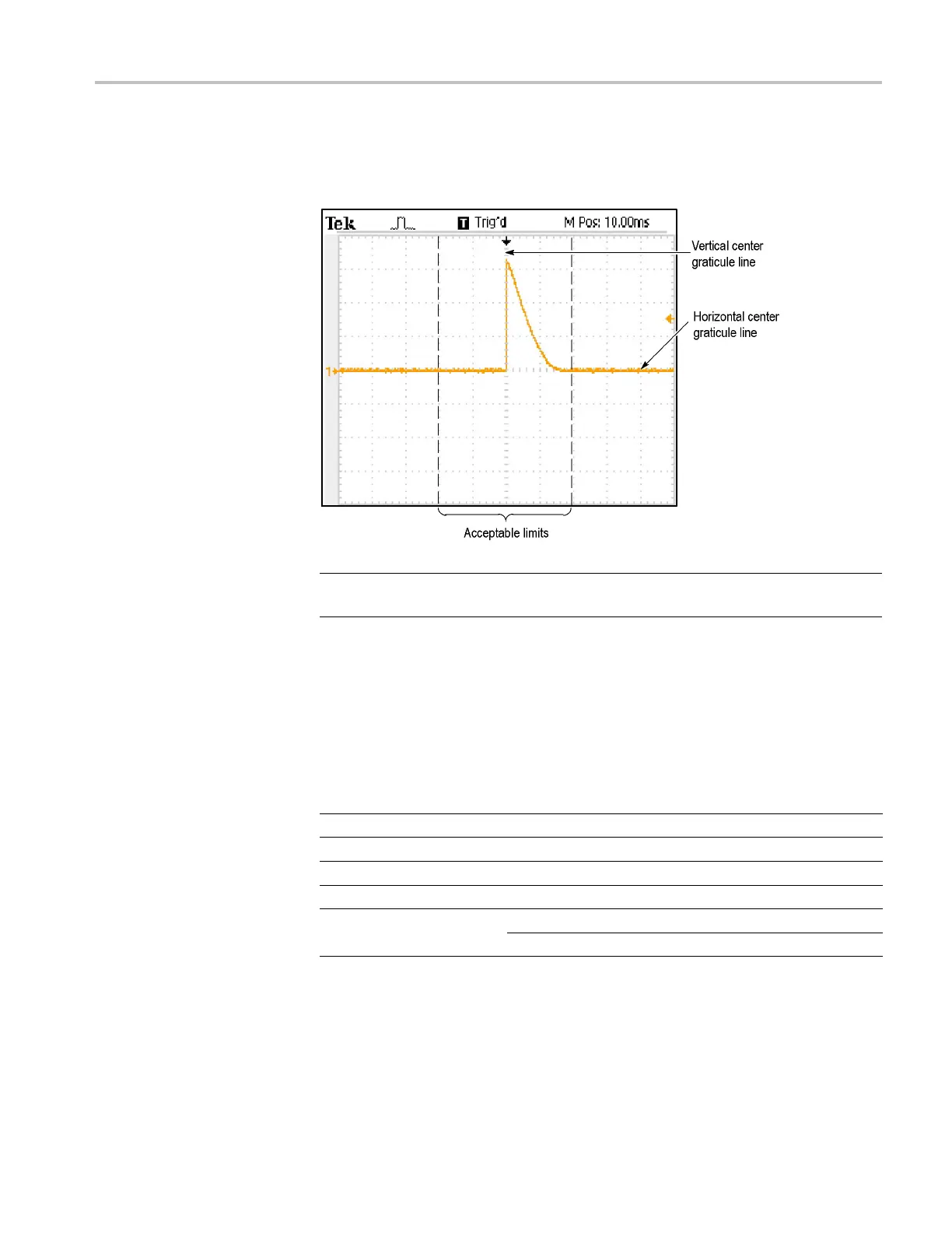
10. Check that the r
ising edge of the marker crosses the center horizontal graticule
line within ±2 divisions of the vertical center graticule line, as shown in the
following figure:
NOTE. On
e division of displacement from graticule center corresponds to a
25 ppm time base error.
11. Disconnect the test setup.
Check
Edge Trigger
Sensitiv ity
This test checks the e dge trigger sensitivity for a ll input channels.
1. Set up the oscilloscope using the following table:
Push
menu button
Sele
ct menu option
Sele
ct setting
Def
ault Setup
——
Cha
nnel 1
Probe 1X
Trig Menu Mode Normal
Acquire
Sample
—
Source Channel under test
Measure
Type Pk-Pk
TDS2000C and TDS1000C-EDU Series Oscilloscope Service Manual 33
 Loading...

