Operating Information Probe Adapter
2
Frequency response flatness from 10 Hz to 100 kHz is strongly dependent on the accuracy of the probe
compensation. It is recommended that each probe be compensated to match the individual Probe
Adapter that it will be used with. This adjustment should be made by observing the effect on the
mid-field transition of a field square-wave signal.
Flatness in the 100 kHz to 10 MHz range varies a great deal between probe types. The Probe Adapter
circuitry is optimized for the Tektronix P6109 10X probe, a common low-cost probe. Other 10X
oscilloscope probes capable of driving a 1 MΩ, 20 pF input may be used, but they can degrade the
flatness of the frequency response.
Two additional effects of making measurements through the Probe Adapter should be noted. First, the
video signal-to-noise ratio is degraded from the VM700A’s typical 82 dB to approximately 73 dB with
the Probe Adapter. Secondly, the Probe Adapter introduces some output offset voltage and some minor
tilt effects due to ac coupling. Both of these effects are normally eliminated by the clamping
capabilities of the VM700A.
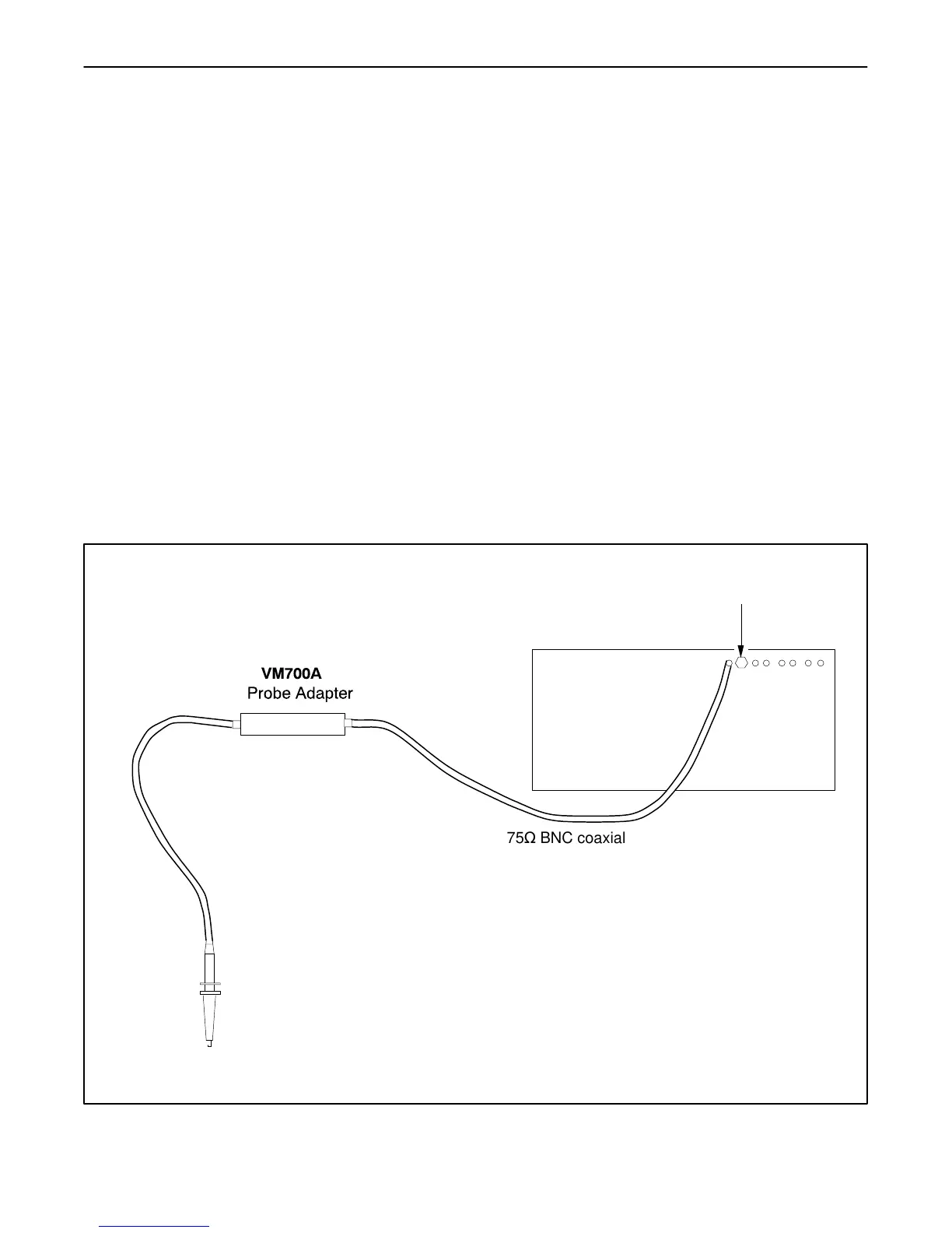
The 1 MΩ 10X probe connector provides a high impedance signal input that produces minimal circuit
loading for the device under test. The output of the probe adapter is at 75Ω to match the input of the
VM700A. Use high quality 75Ω BNC coaxial cable to connect to the VM700A input, and terminate the
signal line with a 75Ω termination at the last device in the signal path as shown in Figure 2.
75W BNC coaxial cable
75W Termination
P6109 10X Probe
To device under test
VM700A
Figure 2. Typical hookup for the Probe Adapter.

 Loading...


