Probe Adapter Operating Information
3
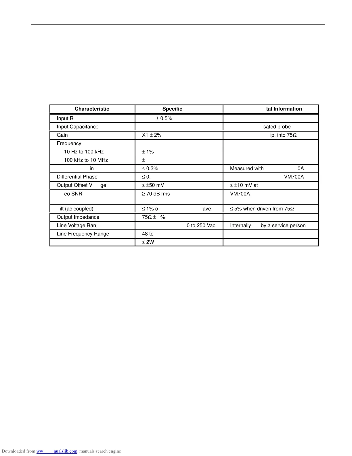
SPECIFICATIONS
The specifications given in Table 1 for gain, frequency response, and tilt are with a P6109 probe that
has been properly compensated for the Probe Adapter with which it is to be used.
Table 1
Specifications
Characteristic
Specification
Supplemental Information
Input Resistance
1 MΩ ± 0.5%
Input Capacitance
20 pF ± 2 pF
Use a compensated probe
Gain
X1 ± 2%
From 10X probe tip, into 75Ω
Frequency Response
10 Hz to 100 kHz
± 1%
100 kHz to 10 MHz
± 1%
Differential Gain
≤ 0.3%
Measured with 1910 or VM700A
Differential Phase
≤ 0.3°
Measured with 1910 or VM700A
Output Offset Voltage
≤ ±50 mV
≤ ±10 mV at 25°C
ÁÁÁÁÁÁÁÁÁ
Video SNR
ÁÁÁÁÁÁÁÁÁ
≥ 70 dB rms
ÁÁÁÁÁÁÁÁÁÁ
VM700A Noise Spectrum, un-
weighted
Tilt (ac coupled)
≤ 1% on a 50 Hz square wave
≤ 5% when driven from 75Ω
Output Impedance
75Ω ± 1%
Line Voltage Range
90 to 132 Vac or 180 to 250 Vac
Internally set by a service person
Line Frequency Range
48 to 62 Hz
Power Consumption
≤ 2W
 Loading...


