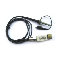
Do you have a question about the Tektronix P6021 and is the answer not in the manual?
Guidelines to prevent injury and product damage during operation.
Emphasizes qualified personnel for service and precautions against solo servicing.
Lists the quantifiable performance limits guaranteed for the P6021 Current Probe.
Outlines the necessary equipment and steps to verify the probe's performance against its specifications.
Details the required preparation and initial setup of test equipment for probe adjustments.
Guides the user through adjusting the probe for optimal fast rise time and minimal waveform aberrations.
Details the procedure for verifying and adjusting the termination's 2 mA/mV sensitivity setting.
Describes how to perform a functional check and adjustment for the 10 mA/mV termination sensitivity.
Step-by-step guide to test the probe's sensitivity at the 2 mA/mV setting using a calibration generator.
Step-by-step guide to test the probe's sensitivity at the 10 mA/mV setting using a calibration generator.
| Bandwidth | 500 MHz |
|---|---|
| Attenuation Ratio | 100:1 |
| Input Impedance | 1 MΩ |
| Maximum Input Voltage | 600 V (DC + AC Peak) |
| Cable Length | 1.5 m |
| Input Resistance | 1 MΩ |


 Loading...