Service Information
20
P6021 Instruction Manual
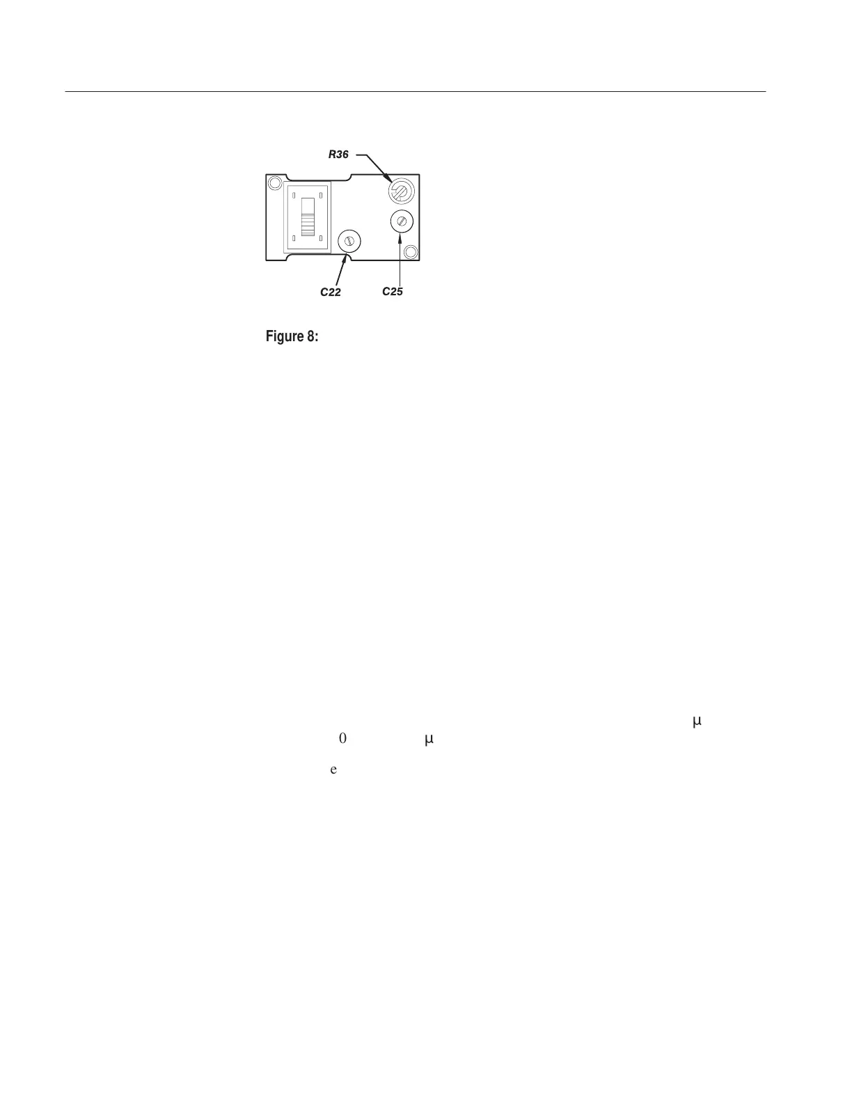
R36
C25
C22
Figure 8: Location of termination adjustments
11. Set the termination sensitivity control to the 10 mA/mV position.
12. Set the oscilloscope vertical deflection to 1 mV/division.
13. Adjust the oscilloscope position, triggering, intensity, and calibration
generator amplitude controls until the signal is centered on the display. Make
certain that you can see the top of the waveform.
14. Check again to make sure that the aberrations are within the specifications
described in Step 9, beginning on page 18.
Termination Sensitivity at 10 mA/mV (Functional Check).
1. If the gated measurement mode is still active, verify the gated zone is for the
full displayed window.
2. Repeat steps 9a through 9f, except set the digital oscilloscope to 1 mV/div
and adjust for a 2.00 mV amplitude display at 50 ns/div.
3. Check aberrations as for the 2 mA/mV position using the gated zone,
peak-to-peak measurements. For this case, 10% = 0.2 mV or 200
m
V;
2% = 0.04 mV or 40
m
V.
Measurement notes:
For the 2% measurement, you may have to increase the averaging to 400 or
greater to minimize noise. If the average reading fluctuates, use the average
of these fluctuations or turn on statistics (if available) and use a weighted
mean value.
Digital oscilloscopes with zoom mode can increase resolution. Noise and
statistical variations will limit the useful resolution.
Turn gating off after completing measurements.
All of the adjustments interact; you may have to repeat adjustments to meet all
specifications.