Installation Instructions
WVR6UP, WVR70UP, and WVR7UP Upgrades
25
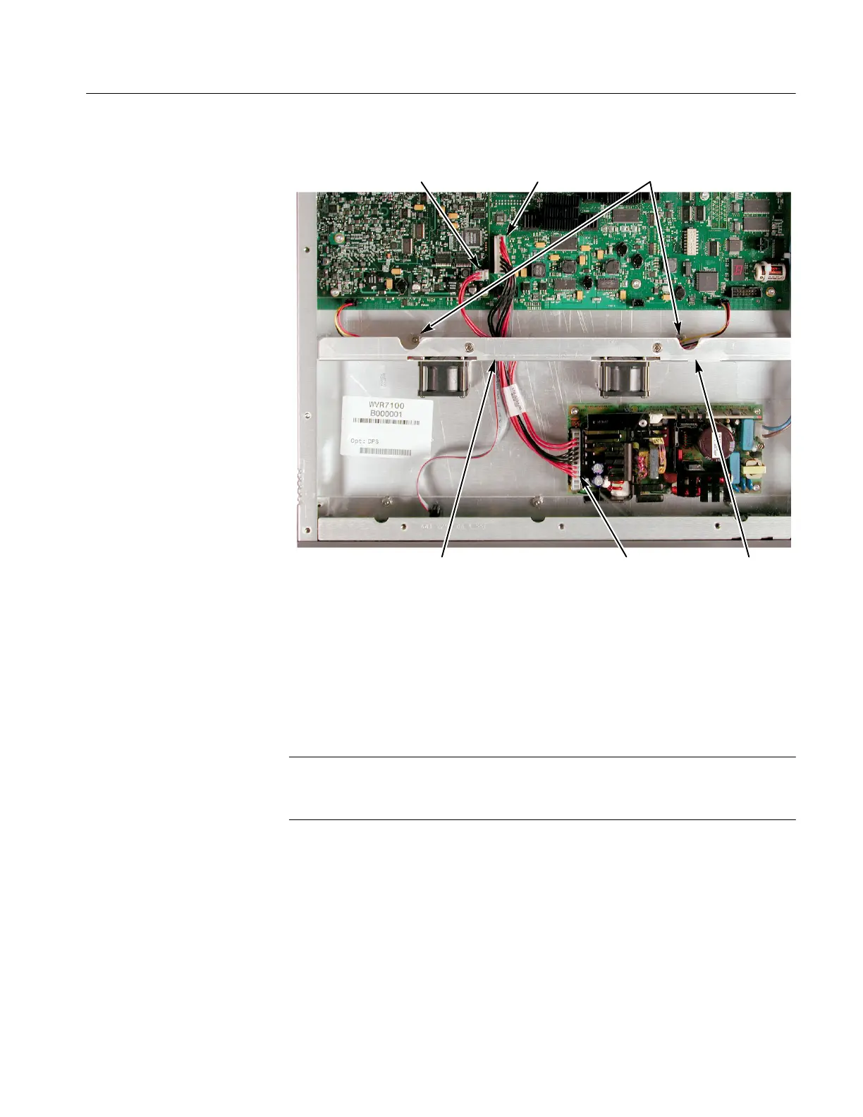
2-wire connector to
J3 on Eye board
7-wire connector to
J570 on Main board
Rectangular
cut-out
9-wire connector to
J2 on Power Supply
Fan bracket
securing nuts
Shield
retaining slot
e. Tighten the two 5/16-inch nuts that secure the fan bracket to the base of
the chassis.
f. If present, reengage the clear plastic Power Supply shield in the retaining
slot in the fan bracket.
Perform the following steps to install the coaxial cables:
NOTE. To gain easier access to the connections on the Loop-through board, you
can disconnect the ribbon cable from the board. If you disconnect the ribbon
cable, be sure to reconnect it when you finish connecting the coaxial cables.
18. Connect one coaxial cable from the J3 connection of the Loop-through board
to the J1 connection of the Eye board.
19. Connect the remaining coaxial cable from the J2 connection of the Loop-
through board to the J2 connection of the Eye board.
20. Verify that the installed Eye board appears as shown below.
WVR7100 Only