TECHNICAL DATA
NO.OFBUTTONS
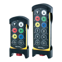
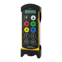
TG-TX-MNL6,TG-TX-MNR6,TG-TX-MNP6 6x2-stepbuttons
TG-TX-MDL10,TG-TX-MDR10,TG-TX-
MDP10
10x2-stepbuttons
BATTERY
TG-TX-MNL6,TG-TX-MNR6,TG-TX-MNP6 Internal,rechargeablelithium-ion
TG-TX-MDL10,TG-TX-MDR10,TG-TX-
MDP10
External,rechargeablelithium-ion
ON/OFFSWITCH
TG-TX-MNL6,TG-TX-MNR6,TG-TX-MNP6 Yes
TG-TX-MDL10,TG-TX-MDR10,TG-TX-
MDP10
No
DUPLEXCOMMUNICATION
TG-TX-MNL6,TG-TX-MNR6,TG-TX-MNP6,
TG-TX-MDL10,TG-TX-MDR10,TG-TX-
MDP10,
Possible
MAX.NOOFREGISTEREDRECEIVERS
TG-TX-MNL6,TG-TX-MNR6,TG-TX-MNP6 4
TG-TX-MDL10,TG-TX-MDR10,TG-TX-
MDP10
8
SIZE
TG-TX-MNL6,TG-TX-MNR6,TG-TX-MNP6 160x76x37mm./6.3x3x1.4in.
TG-TX-MDL10,TG-TX-MDR10,TG-TX-
MDP10
210x76x37mm./8.2x3x1.4in.
WEIGHT
TG-TX-MNL6,TG-TX-MNR6,TG-TX-MNP6 295g./0.6lbs.
TG-TX-MDL10,TG-TX-MDR10,TG-TX-
MDP10
400g./0.9lbs.
OPERATINGFREQUENCY
TG-TX-MNL6,TG-TX-MDL10 433.075-434.775MHz
TG-TX-MNR6,TG-TX-MDR10 903.0125-926.9875MHz
TG-TX-MNP6,TG-TX-MDP10 2405-2480MHz
NO.OFCHANNELS/FREQUENCYBANKS
TG-TX-MNL6,TG-TX-MDL10 69
TG-TX-MNR6,TG-TX-MDR10 15
TG-TX-MNP6,TG-TX-MDP10 16
- 6 -
 Loading...