EasyManua.ls Logo

TELECO AUTOMATION TVSTRD868SI24G - User Manual

TELECO AUTOMATION TVSTRD868SI24G
12 pages
Print Icon
To Next Page IconTo Next Page
Loading...
TELECO AUTOMATION SRL - Via dell’Artigianato, 16 - 31014 Colle Umberto (TV) ITALY
TELEPHONE: ++39.0438.388511 FAX: ++39.0438.388536 - www.telecoautomation.com
This document is the property of Teleco Automation Srl who reserves all reproduction and copying rights
TVSTRD868SI24G Master 3x4A (868.3Mhz)
TVSTRD916SI24G Master 3x4A (916Mhz)
TVSTRD868BSI24G Master 3x4A, Box IP54 (868.3Mhz)
TVSTRD916BSI24G Master 3x4A, Box IP54 (916Mhz)
IT - RICEVITORE RADIO PER IL CONTROLLO DI STRIP LED 1-COLORE ANODO COMUNE
Permette di controllare le 3 uscite in modo indipendente o sincronizzato.
EN - RADIO RECEIVER CONTROLLING 1-COLOUR LED STRIPS COMMON ANODE
Independent or synchronized control of the 3 output.
FR - RECEPTEUR RADIO POUR LE CONTROLE DES LEDS MONOCHROME AVEC ANODE COMMUNE
Possibilité de commander les 3 sorties séparément ou simultanément.
DE - EMPFÄNGER ZUR ANSTEUERUNG VON EINFARBIGEN LED STRIPES – GEMEINSAME ANODE
Es ist möglich die Ausgänge entweder auf unabhängige oder synchronisierte Weise anzusteuern.
IT - Codice prodotto
EN - Product code
FR - Code du produit
DE - Artikelnummer
T1T2T3
L1
-
L2 -
L3 -
Led 1
P1
P2
P3
Led 2
Led 3
Led 4
9
10
11
12
13
14
12-24V
IN
12-24V
OUT
COM
SLAVE OUT
(max. 5 slaves)
1
2
3
4
5
6
7
8
COM
TVRGBD000xST24
Slave 3x4A
DOC.: T546.04
TVSTRDxxxSI24G - TVSTRDxxxBSI24G
DATE: 26/09/16
165 mm
IT - Foro per il fissaggio con vite (sotto lo sportello)
EN - Hole for fixing with screw (under the cover)
FR - Trou pour fixation avec vis (sous le couvercle)
DE - Loch für die Montage mit Schraube (unter dem Deckel)
IT - Montaggio su superficie piana
EN - Flat surface mounting
FR - Fixation sur surface plate
DE - Montage auf ebene Oberfläche
70 mm
185 mm
IT - Foro per il fissaggio con vite (sotto lo sportello)
EN - Hole for fixing with screw (under the cover)
FR - Trou pour fixation avec vis (sous le couvercle)
DE - Loch für die Montage mit Schraube (unter dem Deckel)
IT - Montaggio su superficie piana
EN - Flat surface mounting
FR - Fixation sur surface plate
DE - Montage auf ebene Oberfläche
74 mm (50 mm)
56 mm
151 mm
47 mm
40 mm
IT - Montaggio EN - Mounting FR - Fixation DE - Montage
Question and Answer IconNeed help?

Do you have a question about the TELECO AUTOMATION TVSTRD868SI24G and is the answer not in the manual?

Overview

This document describes the TELECO Automation S.r.l. TVSTRDxxx(x)SI24G and TVRGBD000xST24 devices, which are radio receivers for controlling LED lighting systems.

Function Description

The TVSTRDxxx(x)SI24G is a radio receiver designed to control monochromatic LED strips, while the TVRGBD000xST24 is a slave output unit that extends the control capabilities. These devices allow for the remote control of LED lighting, including on/off functions, dimming, and in the case of RGB systems, color selection. The receivers can be integrated into existing lighting setups, providing a convenient way to manage LED illumination.

The system supports both independent and synchronized output modes. In independent mode, each receiver operates autonomously. In synchronized mode, multiple receivers can be linked to respond to a single command, ensuring uniform lighting control across a larger area. The devices are capable of memorizing radio codes from transmitters, allowing for personalized control setups.

The receivers can operate in various modes:

  • ON/OFF (EIN/AUS): Toggles the LED strip on or off.
  • DIMMER: Adjusts the brightness of the LED strip.
  • Continuous Sound: Indicates a continuous operation or successful memorization.
  • Intermittent Sound: Indicates an intermittent operation or a specific action like deletion.

The system also features a memory for the last intensity value, which can be activated or deactivated. This means the lights can return to their previous brightness setting when turned on, or always start at a default level.

Important Technical Specifications

Power Supply: 12-24V Output: 3 channels Max Power for each output: 4A (50W - 12V, 100W - 24V) Operating Temperature Range: -20°C / +50°C Section of input cable (maximum load): 2.5 mm² Reception Frequency: - TVSTRD868SI24G: 868.3 MHz - TVSTRD916SI24G: 916 MHz Radio Memory Capability (transmitters): 42 Protection Rating: IP20 / IP54 (depending on the model and installation)

The devices are designed to comply with IEC60950-1 and other relevant provisions for safety and electromagnetic compatibility. The power supply must be stable and free from voltage peaks. The product is not designed to be immersed in water or exposed to aggressive chemicals.

Usage Features

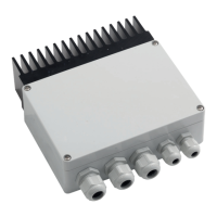
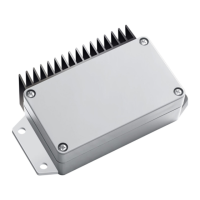
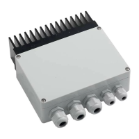
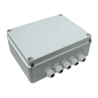
Installation: The receivers are designed for easy installation. They can be mounted on a flat surface using screws. The TVSTRDxxx(x)SI24G has dimensions of 191 mm x 47 mm x 33 mm, while the TVRGBD000xST24 slave unit has dimensions of 191 mm x 70 mm x 33 mm. The devices are suitable for installation in junction boxes or similar enclosures.

Wiring: The devices require a 12-24V power supply. The input cable section should be appropriate for the maximum load. The output channels connect directly to the LED strips. For the TVSTRDxxx(x)SI24G, there are three output channels (L1, L2, L3) and a common positive (+COM). The TVRGBD000xST24 slave unit connects to the master unit and provides additional output channels.

Radio Code Memorization: The receivers can memorize up to 42 radio codes from transmitters. The memorization process involves pressing a button on the receiver (P1) and then transmitting a signal from the remote control. The system provides visual and auditory feedback (LEDs and buzzer) to confirm successful memorization.

  • Single code memorization: Press P1 for 3 seconds, then transmit the code.
  • Multiple code memorization: The receiver can memorize multiple codes within a 15-second window after the initial memorization step.
  • Remote memorization: New codes can be memorized from a distance using an already memorized transmitter. This involves pressing P3 on an existing transmitter and then transmitting the new code.

Radio Code Deletion: Individual or all memorized radio codes can be deleted.

  • Single code deletion: Press P3 on the receiver, then transmit the code to be deleted.
  • All codes deletion: Press P3 on the receiver for 10 seconds.

Control Modes: The receivers support various control commands from compatible transmitters:

  • ON/OFF: A short press (less than 1 second) on the transmitter button toggles the lights.
  • DIMMER: A long press (more than 1 second) on the transmitter button activates the dimming function.
  • Channel Selection: Transmitters with multiple channels (e.g., 7 channels) allow for individual control of different lighting zones or specific functions.

Last Intensity Value Memory: The system can be configured to remember the last brightness level.

  • Activation: Press P1 and P3 simultaneously. The LEDs will flash, and a continuous sound will confirm activation.
  • Deactivation: Press P1 and P3 simultaneously again. The LEDs will flash differently, and an intermittent sound will confirm deactivation.

Maintenance Features

General Maintenance: The devices are designed for long-term reliability and generally require minimal maintenance. Regular checks of the wiring connections are recommended to ensure secure and stable operation.

Troubleshooting:

  • No power to the LEDs: Check the power supply voltage and connections. Ensure the input cable section is adequate for the load.
  • No response from the receiver: Verify the transmitter battery and ensure it is within range. Re-check the radio code memorization process.
  • Interference: The devices are designed to minimize interference, but in some environments, external factors might affect performance. Ensure proper isolation from other electrical components.

Compliance: The product complies with the essential requirements and other relevant provisions of Directive 1999/5/EC. The declaration of conformity can be consulted on the Teleco Automation website.

Safety Warnings:

  • Always disconnect power before installation or maintenance.
  • Ensure proper polarity when connecting the power supply and LED strips. Incorrect polarity can damage the device.
  • The power supply must be stable and free from voltage peaks.
  • The product is not designed for outdoor use unless specifically rated for it (IP54 models).
  • Do not immerse the device in water or expose it to corrosive substances.
  • The housing provides adequate protection against accidental contact and should not be opened by unauthorized personnel.

TELECO AUTOMATION TVSTRD868SI24G Specifications

General IconGeneral
BrandTELECO AUTOMATION
ModelTVSTRD868SI24G
CategoryReceiver
LanguageEnglish

Related product manuals