EasyManua.ls Logo

Teleflex Marine CH2200ENC - User Manual

Default Icon
6 pages
Print Icon
To Next Page IconTo Next Page
Loading...
09/2006 Page 1 of 6 ISCH2200ENC_Rev_0
1. Select a location for the control ensuring that the handle does not
interfere with dashboard, steering wheel, seat, switches, or other
equipment at any point in its travel. NOTE: THICKNESS OF
MOUNTING SURFACE MUST NOT BE GREATER THAN ½”.
Also ensure that the shift cable will have at least 36 inches of
unrestricted space for movement (see INSTALLATION OF
SHIFT CABLE). Refer to Figure 1 for dimensions and
clearances. NOTE: CONTROL CAN BE MOUNTED
HORIZONTALLY OR VERTICALLY TO FACILITATE CABLE
CLEARANCE.
2. Cut mounting holes in selected location, using template provided.
3. If not already routed, route the shift cable and engine harness
to the cutout, allowing the cable and harness to protrude from
the cutout enough to allow connection to the control mechanism.
INSTALLATION OF SHIFT CABLE
1. BEND RADIUS
Minimum bend radius is 8”. If installed with sharper bends, cable
wear will increase rapidly.
2. SUPPORTING THE CABLE
DO NOT TIE OR CLAMP THE CABLE WITHIN 36 INCHES OF THE
CONTROL. WHEN SUPPORTING THE CABLE BEYOND 36
INCHES OF THE CONTROL, DO NOT TIE OR CLAMP TIGHTLY.
THESE INSTRUCTIONS DESCRIBE HOW TO
INSTALL THE CH2200ENC SERIES SIDE MOUNT
CONTROL.
A
DDITIONAL EQUIPMENT REQUIRED:
One Cable - P/Ns CC172XX and CC633XX (CC172 is a 3300-type
cable used for shift in all applications.)
Note: This control does NOT provide “Start in Gear” protection, which must
be provided by the engine manufacturer.
READ THESE INSTRUCTIONS THOROUGHLY BEFORE
STARTING INSTALLATION. FAILURE TO FOLLOW THESE
INSTRUCTIONS AS WELL AS THE INSTRUCTIONS PROVIDED
BY THE ENGINE MANUFACTURER MAY RESULT IN LOSS OF
ENGINE CONTROL WITH SUBSEQUENT PROPERTY DAMAGE
AND PERSONAL INJURY. DO NOT SUBSTITUTE PARTS FROM
OTHER CONTROL MAKERS, AS THEY MAY CAUSE A SAFETY
HAZARD FOR WHICH TELEFLEX, INC. CANNOT ACCEPT
RESPONSIBILITY.
PREPARATION FOR MOUNTING CONTROL
Figure 1
3. CONNECTION OF THE SHIFT CABLE
NOTE: ALWAYS CONNECT THE CABLE TO THE
MECHANISM BEFORE CONNECTING IT TO THE
ENGINE AND GEAR.
1. Push the shift cable through the appropriate retainer,
making sure the cable seats securely into the
retainer (Figure 3, item A).
2. Thread the pivot (Figure 2, item A) onto the cable
terminal until the threaded portion of the terminal
protrudes 5/32” (5 threads). Secure the pivot by
tightening the nut (Figure 2, item B).
3. Connect the pivot to the shifting lever (Figure 3, item
B) and secure with a cotter pin (Figure 3, item C).
Figure 2
A
CH2200ENC
SERIES SIDE MOUNT
SINGLE LEVER CONTROL
Copyright 2006 Teleflex Incorporated (USA)
INSTRUCTIONS
Manufactured by
Teleflex Inc. U.S.A.
640 N. Lewis Road
Limerick, PA 19468 (USA)
610/495-7011
Figure 3
INSTALLER: THESE INSTRUCTIONS CONTAIN IMPORTANT SAFETY INFORMATION AND MUST BE FORWARDED TO THE BOAT OWNER.
WARNING
Question and Answer IconNeed help?

Do you have a question about the Teleflex Marine CH2200ENC and is the answer not in the manual?

Summary

Preparation for Mounting Control

Select Mounting Location

Choose a location ensuring the handle does not interfere with other equipment and the mounting surface thickness is 1/2" max.

Cut Mounting Holes

Cut mounting holes in the selected location using the provided template.

Route Shift Cable and Harness

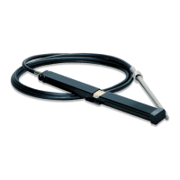
Route the shift cable and engine harness to the cutout, allowing sufficient protrusion for connection.

Installation of Shift Cable

Bend Radius Requirements

Maintain a minimum bend radius of 8 inches to prevent rapid cable wear.

Cable Support Guidelines

Do not tie or clamp cable within 36 inches of the control; support loosely beyond that.

Connect Shift Cable

Connect the cable to the mechanism, ensuring the retainer seats securely and the pivot is properly threaded and secured.

Installation of Wiring Harness

Routing and Securing Harness

Route harness via shortest path, secure every 2 feet, coil excess, and keep away from heat and fluids.

Control Head Wire Harness Preparation

Measure and Prepare Harness

Measure runs, round up to nearest foot, and prepare harness using stranded tinned copper, 18 AWG min.

Wiring Harness Connection

Connect to Control Head

Connect the 6-pin connector from the harness to the control head, ensuring a fully seated and latched connection.

Throttle Brake Adjustment

Adjusting Friction Device

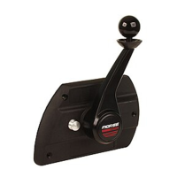
Adjust throttle friction using the screw; turn clockwise to increase, counterclockwise to decrease.

Installation of Control Mechanism

Install Mechanism

Ensure control is in gear and half throttle, then push mechanism flush and secure with four screws.

Handle Assembly Installation

Install Handle

Engage splines fully, install set screw, then attach button and mounting screw securely.

Verify Handle Engagement

Cycle handle through full range to ensure splines are engaged; re-install if necessary.

Connection to Engine

Connect Shift Cable and Harness

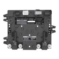
Connect shift cable using kits and connect 10-pin harness connector to engine TAC module securely.

Maintenance Checks

Periodic Inspection

Periodically check control mounting, handle attachment, and cable condition for stiffness or lost motion.

Operation of Control

Throttle Warm-up Procedure

Push button, pull umbrella, advance handle to warm-up mode for engine start and idle.

Shifting Procedure

Pull umbrella, move handle to detent for gear engagement, then advance for throttle control.

Overview

The Teleflex CH2200ENC Series Side Mount Single Lever Control is a marine control system designed for managing engine throttle and shift functions. Manufactured by Teleflex Inc. U.S.A., this control is intended for use with boats and requires a CC172XX or CC633XX cable (CC172 is a 3300-type cable for shift applications). It's important to note that this control does not provide "Start in Gear" protection; this safety feature must be provided by the engine manufacturer.

Function Description

The primary function of the CH2200ENC control is to provide a single lever for both throttle and shift operations. It allows the operator to engage forward or reverse gears and adjust the engine throttle. The control head connects to the engine's TAC module via a wiring harness.

Usage Features

  • Installation: The control can be mounted horizontally or vertically to facilitate cable clearance. The mounting surface thickness must not exceed 1/2". A template is provided for cutting the mounting holes. The shift cable requires at least 36 inches of unrestricted space for movement.
  • Shift Cable Connection: The shift cable connects to the control mechanism via a pivot and cotter pin. It's crucial to connect the cable to the mechanism before connecting it to the engine and gear. The minimum bend radius for the shift cable is 8 inches; sharper bends can rapidly increase cable wear. The cable should not be tied or clamped within 36 inches of the control, and beyond that, it should not be tied or clamped tightly.
  • Wiring Harness Connection: A wiring harness connects the control head to the engine TAC module. Care must be taken to avoid damaging the cable insulation during routing. The harness should be secured every 2 feet (0.6 m) and kept away from high current wires, water, fuel, lubricants, or excessive heat. The 6-pin connector from the harness connects to the potentiometer on the control head, and the 10-pin connector connects to the engine TAC module.
  • Handle Installation: The handle assembly contains two sets of internal splines (on the chrome locking ring and the black handle) that mate with external splines on the control mechanism (on the cast housing and steel shaft). Both sets of splines have 48 teeth and are consistently oriented, allowing the handle to be indexed every 7.5°. The handle is secured with a set screw and a button mounting screw.
  • Throttle Warm-up: To activate engine warm-up, the handle must be in the neutral position (typically vertical). The operator pushes and holds a button, pulls an "umbrella" mechanism up toward the knob, and then advances the handle forward. This puts the control into warm-up throttle mode, allowing throttle adjustment by moving the handle. Returning the handle to neutral disengages warm-up.
  • Shifting: To shift into forward or reverse, the operator pulls the "umbrella" up toward the knob and advances the handle forward (for forward travel) or rearward (for reverse travel). The handle will settle into a detent at approximately 30° of travel, indicating that the gear is engaged and the control has entered throttle mode. Further advancement of the handle increases the throttle. Once in throttle mode, it is not necessary to pull the umbrella.
  • Throttle Brake Adjustment: The control mechanism includes an adjustable friction device (brake) to prevent throttle creep. This can be adjusted by turning an adjustment screw clockwise to increase braking or counterclockwise to decrease it. Adjustments should be made with the control at 1/2 throttle and the gear engaged. The brake does not influence gear shifting.

Important Technical Specifications

  • Mounting Surface Thickness: Not greater than 1/2".
  • Shift Cable Clearance: At least 36 inches of unrestricted space.
  • Shift Cable Bend Radius: Minimum 8 inches.
  • Wiring Harness Wire Gauge: 18 AWG min (stranded tinned copper, UL 1426 or equivalent).
  • Wiring Harness Support: Every 2 feet (0.6 m) with stainless steel screws and mounting head ties or clamps.
  • Handle Indexing: Every 7.5° due to 48-tooth splines.
  • Shift Detent Angle: Approximately 30° of travel from neutral.

Maintenance Features

Although the control system requires very little maintenance, periodic checks are recommended:

  • Mounting Security: Ensure the control is firmly mounted to the boat.
  • Lost Motion Check: If the handle develops lost motion, verify that the handle is firmly attached to the control body, the control body is firmly attached to the boat, and the cables are firmly attached to the control, engine, and gear.
  • Stiffness Check: If operation becomes stiff, disconnect the cable from the engine and check the control's operation. If the stiffness is due to the shift cable, it must be replaced.

Safety Warnings

  • Read all instructions thoroughly before installation.
  • Failure to follow instructions may result in loss of engine control, property damage, and personal injury.
  • Do not substitute parts from other control makers, as this may create a safety hazard.
  • Installer must forward these instructions to the boat owner.

Teleflex Marine CH2200ENC Specifications

General IconGeneral
BrandTeleflex Marine
ModelCH2200ENC
CategoryMarine Equipment
LanguageEnglish

Related product manuals