Software Cont’d
The buttons on the VCP perform the following functions…
* Range: Allows switching the maximum power range of the display. Choices are 25, 250, 2500W and Auto for autoranging.
* Alarm: Sets the SWR Alarm set point. Choices are Off,1.5,2.0,2.5,3.0. If the alarm on the LP-100A trips, the Alarm button turns red.
* Peak/Avg/Tune: Switches between normal and peak-hold modes. The current mode is displayed under the power reading.
There are two other versions coming for use with TRX-Manager. The first, called LP-100A VCP Slave, allows the LP-100A to broadcast its data to TRX-
Manager for display inside TRX-Manager, either locally or over the internet. The other, LP-100A VCP Master, allows the LP-100A to use TRX-Manager’s
remote telnet facility to make a remote connection between the LP-100A and the VCP. In addition to the LP-100A VCP, you can communicate with the
LP-100A with a terminal program or your own software using the following commands…
A Increments Alarm Set Point selection
M Increments Mode selection
F Toggles Power Peak/Avg/Tune selection
P Poll for data. Example of response… ;1457.00,49.3,005.0,2,N8LP ,0,2,61.6,1.02
From left to right, the comma separated values represent…
Power, Z, Phase, SWR Alarm Set Point: 0=off, 1=1.5, 2=2.0, 3=2.5, 4=3.0, Callsign (6 digits with space padding), Power range: 0=High, 1=Mid, 2=Low,
Peak Hold Mode: 0=Average, 1= Peak Hold, dBm, SWR
Note: The commands for firmware version 1.2.0.0 and above are different than those for earlier versions. I have added an option in the Setup section of
VCP, Plot and TRX-Slave to allow use with versions of firmware that are earlier or later than 1.2.0.0. If you need to see the old protocol, or have
developed software to work with the LP-100A, you should refer to an older manual to see the differences.
The serial settings are 115,200 baud, 8 bits, no parity, 1 stop bit. NOTE: Firmware versions before 1.2.0.0 used a baud rate of 38,400, and before 1.0.3
used a baud rate of 19,200 and did not report dBm or SWR values.
MicroCode Loader
Before attempting to flash new firmware, make sure the connection between the LP-100A and PC is solid. You can do this by running the VCP program.
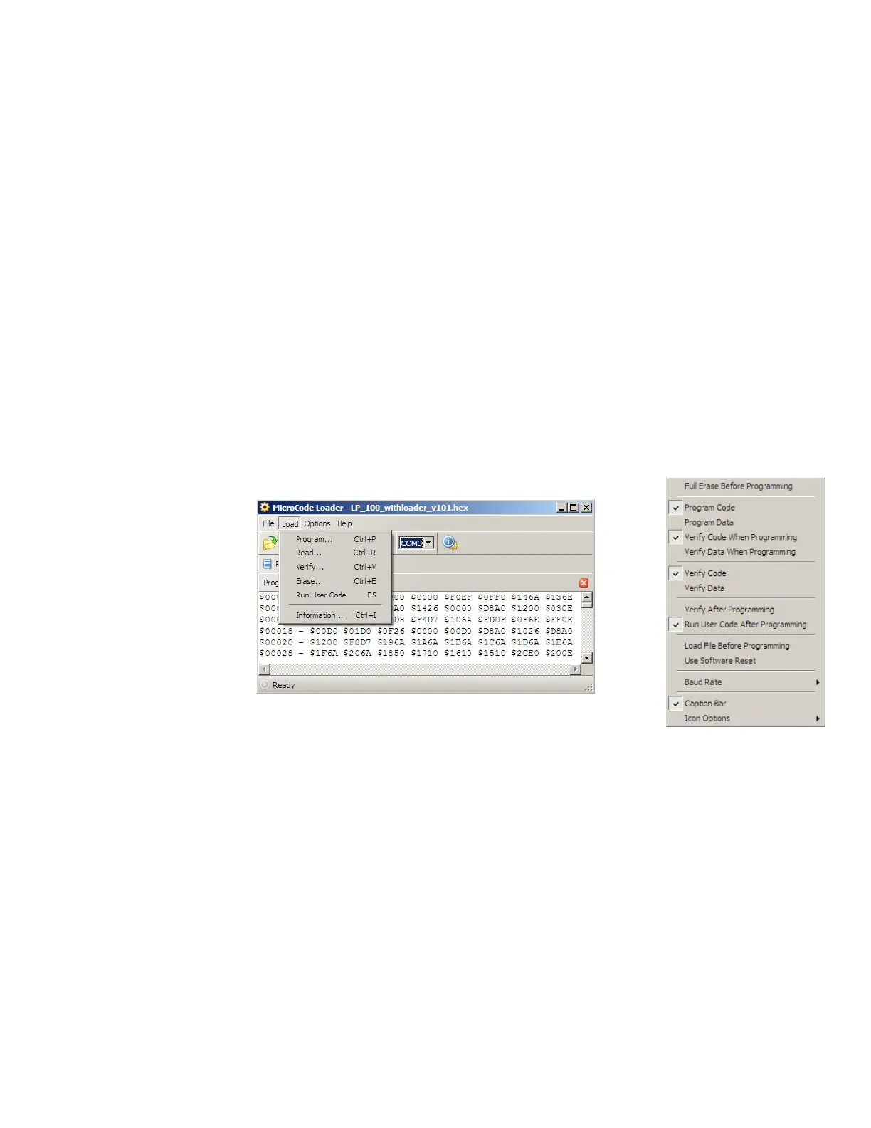
MicroCode Loader works with the MCLoader bootstrap loader program installed on your PIC. It allows the user to easily update the firmware in the LP-
100A. The correct settings for MicroCode Loader, found under the Options pulldown, are as shown. NOTE: Make sure you settings match these before
starting. If you select Program Data, the factory defaults will be loaded into your CAL constant table.
All that is required is to download the latest version of the firmware from my website, save it to a convenient folder, such as C:\Program Files\LP-100A-
VCP\Updates and then load the file into MCLoader using the File>Open menu. Note: It is important to open the file you want each time you launch
MCLoader, or else it will start up with the last used file, and you may forget to open a new file and reprogram your LP-100A with an older version. It is
even possible that you might have a file from another device loaded, since MCLoader is used by other manufacturers as well.
Once MCLoader is running, and you have the correct firmware file open, you need to set the correct LP-100A com port for the LP-100A. The default
baud rate of “Auto” should be fine, but if you experience problems, you may want to try setting baud rate to 19,200 (under Options). When all of this is
done, click on Load>Program. You will see a message to Reset the PIC. This is done by cycling the power to the LP-100A. A progress bar in MCLoader
will show the progress of the programming, and the LP-100A will start again when programming is finished. The “Splash” screen will now indicate the
new version at startup. During programming, the LP-100A displays “PIC Reset” if the software reset is used.
 Loading...