EasyManua.ls Logo

Televes 5310 User Manual

Televes 5310
4 pages
To Next Page IconTo Next Page
Page #1 background imageLoading...
Page #1 background image
Central Amplificación Separada
Central Amplificação Separada
Amplif. à voies VHF et UHF Séparées
Compact Split-Band Amplifier
Ref. 5310
MATV
234503
Split-Band Amplifier
Salida
Output
Central Amplificación Separada
Test
(-30dB)
FM
-20 0
BI / BIII
(24 Vdc)
-20 0
UHF
(24 Vdc)
-20 0
Central de 3 entradas con
amplificación separada (UHF,
BIII/BI y FM), realizada en chásis
de zamak para ser utilizado en
cabeceras de MATV.
Central de 3 entradas com
amplificação separada (UHF,
BIII/BI e FM), realizada em chas-
sis de zamak para ser utilizado
em cabeceiras de MATV.
Centrale de 3 entrées à voies
séparées (UHF, BIII/BI et FM),
fabriquée en chassis zamak,
pour utilisation en ligne de tête
de MATV.
This is a 3 input ports "compact
amplifier" based on a split-band
amplification philosophy (UHF,
BIII/BI and FM) enclosed into a
robust diecast chassis.
Intended for MATV headends.
234503
Split-Band Amplifier
Salida
Output
Central Amplificación Separada
Test
(-30dB)
FM
-20 0
BI / BIII
(24 Vdc)
-20 0
UHF
(24 Vdc)
-20 0
© Copyright, Televés S.A.
Salida Test
Saída Test
Sortie Test
Output Test
(-30dB)
230~ 15% 50Hz
Entradas / Entradas / Entrées / Inputs
UHF BIII/BI FM
Regulación de niveles de entrada
Regulação de niveis de entrada
Réglage du niveau d’entrée
Input level attenuators
Salida
Saída
Sortie
Output
LED de encendido
LED de encendido
LED ON
ON LED
Fig. 1
Fig. 2
Split-Band Amplifier
Central Amplificación
Test
(-30dB)
BI / BIII
(24 Vdc)
-20 0
UHF
(24 Vdc)
-20 0
Question and Answer IconNeed help?

Do you have a question about the Televes 5310 and is the answer not in the manual?

Televes 5310 Specifications

General IconGeneral
Model5310
TypeAmplifier
Frequency Range47-862 MHz
Gain20 dB
Power Supply12 V DC
Noise Figure5 dB
ConnectorsF-type

Summary

Important Safety Instructions

General Installation Conditions

Covers requirements and precautions for safe equipment installation, avoiding rain, moisture, and heat.

Safe Equipment Operation

Details safe operational practices, power connection, and disconnection procedures.

Electrical Safety Symbol Description

Explains electrical safety symbols and their meaning for user safety, such as risk of shock.

Technical Specifications

Starting Up

Connecting Inputs and Balancing Signals

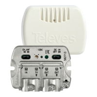
Introduce connectors to inputs and balance signals using front attenuators for correct levels.

Output Signal Level Adjustment

Check output signals, use external attenuators if signal levels are too high for balancing.

Application Example

Installation Recommendation

Avoid powering on the amplifier until all installation connections have been completed.

Declaration of Conformity

Related product manuals