Do you have a question about the Telguard TG-7 Series and is the answer not in the manual?
Register for cellular service via the 24/7 dealer portal.
Confirm adequate cellular signal strength using LEDs.
Verify alarm panel programming for central station communication.
Connect panel, transmit alarms via cellular network, verify activation.
Wire and test Telguard's supervisory trip outputs to the alarm panel.
Wire an external relay input to the trip input lead and ground.
Attach earth ground, reconnect Telco, and permanently mount the unit.
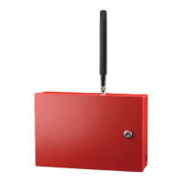
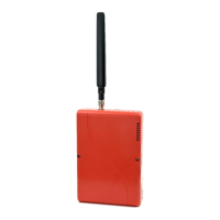
The Telguard TG-7 Series is a communication device designed to transmit alarm signals, primarily over a cellular network, serving as a backup or sole path for alarm communication. It is intended for use in security and fire alarm systems, ensuring that critical signals reach a central monitoring station even if traditional telephone lines are compromised.
The core function of the TG-7 Series is to provide reliable and secure transmission of alarm signals. It acts as an interface between an alarm control panel and a central monitoring station. In its "Backup Mode," the device monitors the existing Telco (telephone line) connection from the alarm panel. If the Telco line fails or is cut, the TG-7 automatically switches to the cellular network to transmit alarm signals. In "Sole Path Mode," the device completely replaces the traditional Telco connection, sending all alarm signals exclusively over the cellular network. This dual functionality ensures flexibility in deployment, catering to different security requirements and existing infrastructure.
The device incorporates a digital dialer output, allowing it to receive alarm signals from the control panel in a format compatible with cellular transmission. It then converts these signals and sends them over its integrated cellular radio. The TG-7 also provides supervisory trip outputs, which can be wired to the alarm panel to indicate the status of the cellular connection or other supervisory conditions. An optional trip input allows for external relay inputs, expanding its integration capabilities with other security components.
A key feature is its ability to measure and display cellular signal strength (RSSI – Received Signal Strength Indicator) through a series of LEDs. This allows installers to optimize placement for the best possible cellular reception, which is crucial for reliable communication. The device also includes various status LEDs that provide visual feedback on its operational state, including activation status, system trouble, panel communication, TMC (Telguard Monitoring Center) communication, radio status, and power status. These LEDs are essential for troubleshooting and verifying proper operation during installation and maintenance.
The TG-7 Series is designed to be a robust and dependable component of an alarm system. It includes a battery connector for an optional backup battery, ensuring continued operation during power outages. This power redundancy is vital for maintaining alarm communication in emergency situations. The device also features an antenna for cellular communication and an RJ31X jack for connecting to the Telco line (in backup mode) or directly to the alarm panel (in sole path mode).
The installation process for the Telguard TG-7 Series is structured into seven distinct steps, emphasizing a methodical approach to ensure proper setup and functionality.
Registration for Cellular Service: Before physical installation, the device must be registered for cellular service through Telguard's dealer portal. This step activates the cellular communication capabilities.
Locate Unit and Measure Signal Strength (RSSI): Installers must first determine the optimal placement for the unit by measuring cellular signal strength. This is achieved by pressing the LED/RSSI Mode Toggle button, which causes the LEDs to display the RSSI. A minimum recommended signal strength (indicated by 2 or 2.5 solid LEDs) is required for reliable operation. This step is critical to prevent communication failures due to poor cellular reception.
Transmit Panel Alarms Over the Telco Connection (Backup Mode) / Configure Alarm Panel for Sole Path Connection (Sole Path Mode):
Program, Activate & Transmit Panel Alarms Over the Cellular Radio Network: This step involves connecting the alarm panel's digital dialer output to the TG-7. The installer then verifies that alarm signals can be reliably sent over the cellular network to the central station. A minimum of two alarm signals must be transmitted. The first alarm activates the unit at the Telguard Communication Center, while subsequent signals are sent to the central station. Activation is confirmed when LED 1 illuminates.
Connect Supervisory Trip Outputs: The TG-7's supervisory trip outputs are wired to the alarm panel. These outputs provide feedback to the panel regarding the status of the cellular connection, allowing the panel to report any issues. After wiring, these outputs must be tested.
Connect Trip Input (Optional): An external relay input can be wired to the trip input lead and ground, providing an additional input for monitoring or control. This feature is optional and depends on the specific system requirements.
Complete the Installation: The final step involves attaching the earth ground, reconnecting the Telco line (if in backup mode), and permanently mounting the unit. This ensures the device is properly grounded and secured.
The device's LED indicators provide comprehensive status information, allowing installers and technicians to quickly assess its operational state. For example, a flashing "Activation Denied" LED indicates an issue with cellular service activation, while a flashing "Radio Communicating" LED shows active data transmission. The "System Trouble" LED flashes in different patterns to indicate specific issues like AC low/missing, low battery, line fault, no service, radio failure, dial tone failure, or panel presence failure.
The TG-7 Series is designed for low maintenance, with its primary maintenance features revolving around visual inspection and troubleshooting using the onboard LEDs.
Overall, the Telguard TG-7 Series is engineered for straightforward installation and reliable, long-term operation, with its diagnostic LEDs serving as the primary interface for ongoing monitoring and troubleshooting.
| Model | TG-7 Series |
|---|---|
| Operating Temperature | 32°F to 120°F (0°C to 49°C) |
| Network Support | Cellular |
| Cellular Technology | LTE |
| Compatibility | Compatible with most fire alarm control panels |
| Communication Protocols | Contact ID, SIA |