EasyManuals Logo

Telit Wireless Solutions LM940 Design Guide

Telit Wireless Solutions LM940
75 pages
To Next Page IconTo Next Page
To Previous Page IconTo Previous Page
Page #48 background imageLoading...
Page #48 background image
LM940 Hardware Design Guide
1VV0301352 Rev. 18 Page 48 of 75 2022-01-04
Not Subject to NDA
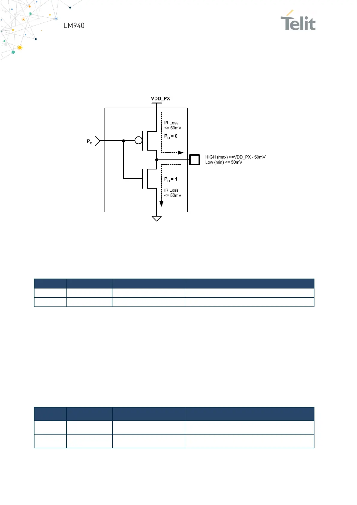
6.6.4.2. Using a GPIO Pin as Output
GPIO pins, when used as outputs, can drive 1.8V CMOS digital devices or compatible
hardware. When set as outputs, the pins have a push-pull output, and therefore the pull-
up resistor can be omitted.
Figure 18: GPIO Output Pin Equivalent Circuit
6.6.4.3. Dedicated I/O
To use SIMIN functions, host must use GPIO_01/GPIO_02.
Pin
Signal
IO/Level
Dedicated Function
3
GPIO_01
Input/1.8V
Can be used as SIMIN1 function
5
GPIO_02
Input/1.8V
Can be used as SIMIN2 function
Table 31: Dedicated I/O
Below functions are not dedicated to specific GPIO.
Customer use one of GPIOs (GPIO_03 to GPIO_08) as these functions by AT command.
Boot OK
Shutdown Indicator
Shutdown Trigger
Dying Gasp Trigger
Pin
Signal
IO/Level
Dedicated Function
44
GPIO_03
I/O, 1.8V
Can be used as specific functions.
46
GPIO_04
I/O, 1.8V
Can be used as specific functions.

Other manuals for Telit Wireless Solutions LM940

Questions and Answers:

Question and Answer IconNeed help?

Do you have a question about the Telit Wireless Solutions LM940 and is the answer not in the manual?

Telit Wireless Solutions LM940 Specifications

General IconGeneral
BrandTelit Wireless Solutions
ModelLM940
CategoryWireless modules
LanguageEnglish

Related product manuals