EasyManuals Logo

Telit Wireless Solutions LM940 Design Guide

Telit Wireless Solutions LM940
75 pages
To Next Page IconTo Next Page
To Previous Page IconTo Previous Page
Page #53 background imageLoading...
Page #53 background image
LM940 Hardware Design Guide
1VV0301352 Rev. 18 Page 53 of 75 2022-01-04
Not Subject to NDA
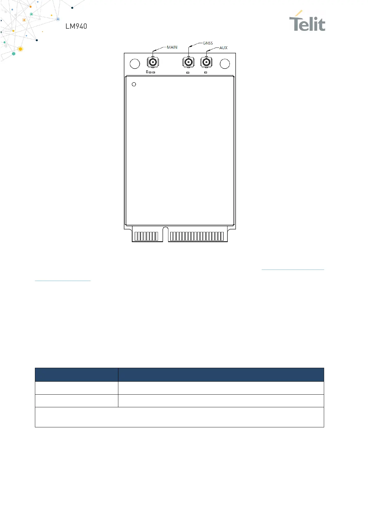
Figure 19: Antenna Connectors Positions
For more information about mating connectors visit the website
http://www.hirose-
connectors.com/
7.5.2. Antenna Cable
Connecting cables between the module and the antenna must have 50 Ω impedance.
If the impedance of the module is mismatched, RF performance is reduced significantly.
If the host device is not designed to use the module’s diversity or GNSS antenna,
terminate the interface with a 50Ω load.
Item
Value
Impedance
50 Ohm
Max cable loss
0.5 dB
Note:
Avoid coupling with other signals.
Table 37: Minimize Antenna Cable Requirements

Other manuals for Telit Wireless Solutions LM940

Questions and Answers:

Question and Answer IconNeed help?

Do you have a question about the Telit Wireless Solutions LM940 and is the answer not in the manual?

Telit Wireless Solutions LM940 Specifications

General IconGeneral
BrandTelit Wireless Solutions
ModelLM940
CategoryWireless modules
LanguageEnglish

Related product manuals