1-800-433-4047 | CL102258-04092020Tell Manufacturing | A Division of Spectrum Brands Inc. 1
INSTRUCTIONS AND TEMPLATE FOR
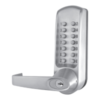
CL600 PK PANIC KIT
MECHANICAL LOCK
READ AND FOLLOW
INSTRUCTIONS CAREFULLY.
Incorrect installation or adjustment
could cause damage or injury.
1. Fit Rubber gasket onto the back of Lock Trim .
2. Screw 3 Lock Trim Posts into back of Lock Trim and tighten.
3. Screw 2 Exit Device Posts to the Cover Plate plate and tighten.
4. Fit Cover Plate over the 3 Lock Trim Posts .
5. Attach the Lock Trim to the door using the 2 Bolts and Washer Plate on top and 1 Bolt and Metal
Flange through the 2-1/8” door prep.
(If no door prep, follow template instruction to drill proper holes)
6. Using the correct Spindle, marked L for left hand or R for right hand, fit the spindle set through
the door and insert it to the spindle hole on the Lock Trim.
7. Hold panic device to the door, aligning holes and spindle. Secure to Lock Trim Thru-bolts.
8. Attach the panic device – sold separately.
Lock Trim
Rubber
Gasket
Cover
Plate
Exit Device
(not supplied)
Spindle
(marked
L or R)
Lock
Trim
Posts
Thru-Bolts
(not supplied
w/lock trim)
Thru-Bolts
Exit Device
Bolts
(supplied)
Exit Device
Posts
Lock Trim
Bolts
Metal
Flange
Washer Plate
CL600 Mechanical Lock Trim
Using the template on page 2, install the CL600 Lock Trim with the Exit Device. Tape
template to the door, mark the holes and drill where needed.