5
2.1 DISCONNECTIONS FROM THE MAIN SUPPLY
The device is disconnected from the main supply in the following order: primarily peripheral devices are
disconnected and lastly the device. For example:
• In the AC main supply the relays circuit is disconnected by short-circuit back-up protection device
SF2, later the device and all sensors are disconnected by SF1 (figure 6.4.1).
• In the DC main supply the relays circuit is disconnected by SF2, later the device and all sensors
are disconnected by SF1 (figure 6.4.2).
• When PC is connected to the device, the computer is disconnected firstly and only later SF1
(figure 7.3.1).
3 INTRODUCTION
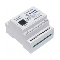
TWCT22 is a compact alarm monitoring and remote control device for electronic equipments with
support of Short Messages (SMS), phone calls, e-mails and GPRS connections. The device is
configurable through internal WEB server interface via GSM network and RS232 interface. Multiple
users can interrogate TWCT22 or be notified on configurable events.
4 TECHNICAL SPECIFICATION
• Supply 11-29V 500mA
• Power consumption max 7W
• Wireless modem:
o Dual Band GSM 900/1800MHz
• 4 digital inputs
o Input resistance 10kΩ
o
“0” (false) 0 – 3Vdc
o “1” (true) 3 - 26Vdc
o Connector: terminal blocks
• 2 analog inputs.
o Voltage mode
Input resistance 60kΩ
Voltage range: 0 – 10Vdc
o Current mode
Input resistance 480 +/-2%kΩ
Current range: 4-20mA
o Resolution 10bit A/D converter
o Connectors: terminal blocks
• 4 relay outputs
o Rated load 240V 50Hz ~7A, 24V 10A
o Total current 20A
o Connectors: terminal blocks
• Interfaces
o RS232
S
peed: 115200 bauds
F
ormat: 8 bits
Parity: none
Stop bits: 1


 To Next Page