8
6 CONNECTORS PIN-OUT
6.1 CONNECTORS FRONT UP PIN-OUT
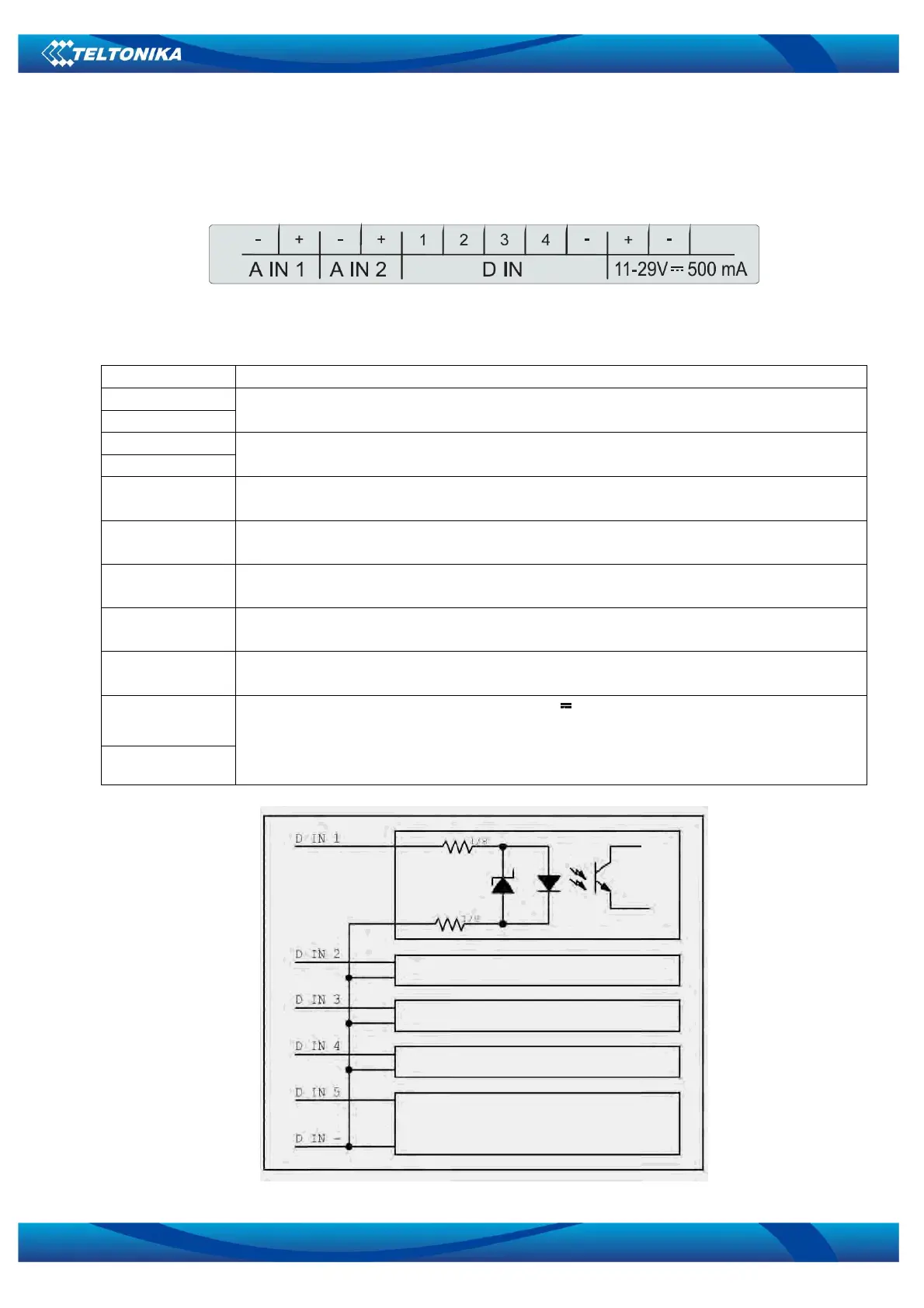
Figure 6.1.1
Table 6.1.1. Connector pin-out
Pin name Description
A IN 1 -
A IN 1 +
Analog input 1. Input voltage range is from 0 to 10Vdc in voltage mode or input
current range is 4-20mA in current mode.
A IN 1 -
A IN 1 +
Analog input 2. Input voltage range is from 0 to 10Vdc in voltage mode or input
current range is 4-20mA in current mode.
D IN 1 Digital input 1. This input is optically isolated by two different voltage levels:
0…3Vdc – false; 3…26Vdc – true.
D IN 2 Digital input 2. This input is optically isolated by two different voltage levels:
0…3Vdc – false; 3…26Vdc – true.
D IN 3 Digital input 3. This input is optically isolated by two different voltage levels:
0…3Vdc – false; 3…26Vdc – true.
D IN 4 Digital input 4. This input is optically isolated by two different voltage levels:
0…3Vdc – false; 3…26Vdc – true.
D IN -
Digital input ground. It is separated from module ground (power supply,
analog input) because digital inputs are optically isolated.
11-29V +
11-29V -
Device supply. Voltage is 11- 29V ±10% 500mA. As switched power
regulator is used inside, the smaller the voltage, the bigger the current and
vice versa (power consumption remains about the same)
Figure 6.1.2


 To Next Page