WARNING:
WARNING:
WARNING:
BEFORE PROCEEDING WITH REPAIRS TO
THE MACHINE READ THE INSTRUCTION
MANUAL CAREFULLY.
EXTRAORDINARY MAINTENANCE SHOULD
BE CARRIED OUT ONLY AND EXCLUSIVELY
BY EXPERT OR SKILLED ELECTRICAL-
MECHANICALPERSONNEL.
ANY CHECKS CARRIED OUT INSIDE THE
MACHINEWHEN IT IS POWERED MAY CAUSE
SERIOUS ELECTRIC SHOCK DUETO DIRECT
CONTACTWITHLIVEPARTS.
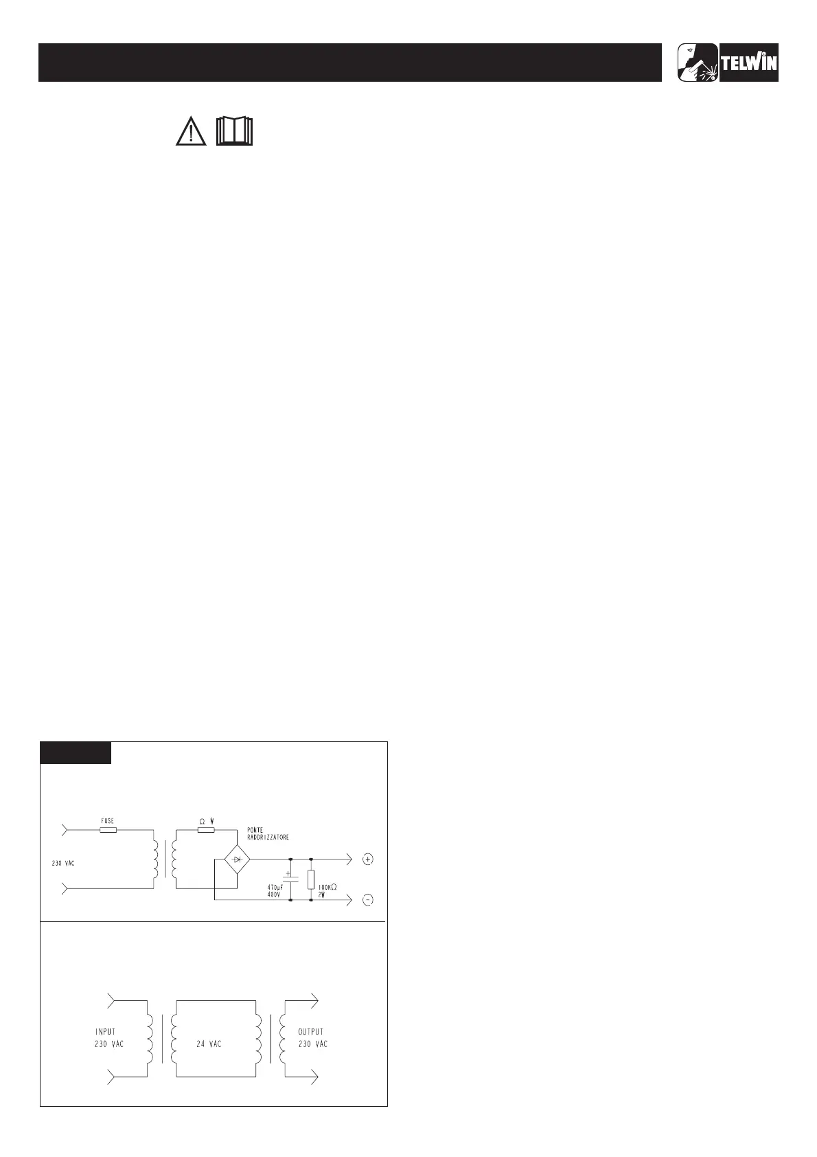
HV POWER SUPPLY MODULE
THE HV POWER SUPPLY is used to ensure operation of the
switching power supply (the circuit on the primary board supplying
auxiliary voltages), even when the machine is operating at low
voltage.
It is easy to build using the electrical diagrams in fig. A for
reference and using the following components or, alternatively, it
canbeorderedfromTelwin.
T1=insulationtransformer230-230V 50VA(*)
D1=rectifierbridge36MB80 (cod.112357)
C1= electrolytic capacitor470uF 400V ALL
(cod.112514)
R1= resistor 10ohm 5W 5%
R2= resistor 100Kohm 2W 5%
F1= delayedaction fuse 1.5 A Fuseholder 5X20mm
Female redand blackfaston
Plasticbox.
The following is a list of practical rules which must be strictly
adheredto if repairsare to be carried out correctly.
A) When handling the active electronic components, the IGBT's
and Power DIODES in particular, take elementary antistatic
precautions (use antistatic footwear or wrist straps, antistatic
working surfacesetc.).
B) To ensure the heat flow between the electronic components
and the dissipator, place a thin layer of thermo-conductive
grease (e.g. COMPOUND GREASIL MS12) between the
contactzones.
C) The power resistors (should they require replacement) should
alwaysbe soldered atleast 3 mmabovetheboard.
D) If silicone is removedfrom some points on the boards,it should
be re-applied. Use only non-conducting neutral or oximic
reticulating silicones (e.g. DOW CORNING 7093). Otherwise,
silicone that is placed in contact with points at different
potential (rheophores of IGBT's, etc.) should be left to
reticulatebeforethe machineis tested.
E) When the semiconductor devices are soldered the maximum
temperature limits should be respected (normally 300 Cfor no
morethan 10 seconds).
F) It is essential to take the greatest care at each disassembly
andassemblystage forthevarious machine parts.
G) Take care to keep the small parts and other pieces that are
dismantled from the machine so as to be able to position them
in the reverse order when re-assembling (damaged parts
should never be omitted but should be replaced, referring to
thespare parts list givenat the end of this manual).
H) The boards (repaired when necessary) and the wiring should
neverbe modifiedwithout prior authorisationfromTelwin.
I) For further information on machine specifications and
operation,refertothe InstructionManual.
J) When the machine is in operation there are
dangerously high voltages on its internal parts so do not touch
theboards when themachine is live.
Every operation should be carried out in complete
safety with the power supply cable disconnected from the mains
outlet:
- Undo the 8 screws fastening the 2 plastic covers (4 each) to the
frontand back .
- Undo the 8 screws fastening the top cover to the structure
.
- Slide out the topcoverbypullinggently outwards .
After completing the repairs, proceed in the reverse order to re-
assemble the cover and do not forget to insert the toothed washer
onthe groundscrew.
Using suitably dried compressed air, carefully clean the
components of the power source since dirt is a danger to parts
subject to high voltages and can damage the galvanic separation
betweenthe primary andsecondary.
To clean the electronic boards we advise decreasing the air
pressureto preventdamage to thecomponents.
It is therefore important to take special care when cleaning the
followingparts
Check whether dirt has been deposited on the front and back air
vents or has damaged the correct rotation of the blades, if there is
stilldamage after cleaningreplace the fan.
rheofores ofIGBT's Q1, Q2,Q3, Q4;
rheofores ofrecirculating diodes D4, D8;
rheofores ofsnubbernetworkdiodes D1, D6;
GENERAL REPAIR INSTRUCTIONS
TROUBLESHOOTING AND REMEDIES
N.B.
WARNING!
WARNING!
(figure1A)
(figure1B)
(figure1B)
-
-
-
°
1.0 Disassembling the machine
2.0 Cleaning the inside of the machine
Fan fig. 2B
Primary board (fig. 3:)
()
-11-
10 5
F1
R1
R2
D1
T1
FIGURE A
TECHNOLOGY 150-170-200-186CE/GE
TECHNOLOGY 150-170-200-186CE/GE
ELECTRICAL DIAGRAM FOR POWER SUPPLY (HV OUTPUT):
THE INSULATION TRANSFORMER CAN BE REPLACED WITH
TWO TRANSFORMERS OF THE SAME POWER,
CONNECTING THE SECONDARIES ACCORDING TO THE
FOLLOWINGDIAGRAM: