- yellowled alarm is turnoff.
Make sure the waveform shown on the oscilloscope
resembles .
if there is no signal it may be necessary to replace the
integratedcircuitU2 or IGBTQ10 on the primaryboard ( ).
C) Set up the multimeter in volt mode and make sure the primary
boardhas the followingvoltages:( ):
- betweenthe cathode of diode D32 (+) and the negativeof diode
bridge D5 (-):equalto +15Vdc 3%;
- between pin 3 (+) and the dissipator (-) of U4: equal to +12Vdc
5%;
- betweenpin 3(+) and pin1 (-) of U6:equal to -12Vdc 5%;
- betweenpin 8(+) and pin7 (-) of ISO1:equal to +26Vdc 5%;
- betweenpin 8(+) and pin7 (-) of ISO2:equal to +26Vdc 5%;
D) Switch off the HV powersupply.
E) Set up the oscilloscope with the voltage probe x10 connected
between the gate (probe) and the emitter (earth) of IGBT Q4 on
theprimaryboard ).
F) Switch on the HV power supply (HV out) and make sure the
waveform displayedon the oscilloscoperesembles .
G) Repeat this teston Q1, Q2,Q3 as well.
if the signal is not present there could be a fault in the IGBT
driver circuit, specifically ISO1 and ISO2 ( ), or in the hybrid
board( , in whichcase werecommend replacing the board).
H) Switch off the HV and replace the 2 fastons connecting the
primary boardand the powertransformer (CN3 and CN10).
I) Switch on the HV and the variac (initially set to 0V), close the
main power supply switch on the machine and gradually increase
thevoltagegenerated bythevariac untilit reaches 26Vac.
J) Set up the oscilloscope with the voltageprobe x100 connected
between the collector (probe) and the emitter (earth) of IGBT Q4
onthe primary board ( ).
K) Make sure the waveform shown on the oscilloscope
resembles
L) Repeat thistest on Q2as well, using the differentialprobe.
If the signal is not present there may be a fault in the IGBT's
().
M) Return the variac voltage to 0V, switch off the machine and the
HVpowersupply.
N) Disconnect the HV power supply, replace jumper JP1 on the
board.
P) Increase the voltage on the variac to 230Vac and make sure
thealarm ceases(yellowLED D9goes off).
Q) Increase the voltage on the variac yet again to 275Vac 5%
and make sure the machine registers an alarm again. Return the
variac voltage immediately to 230Vac and switch off the machine.
if an alarm persists (and is not caused by a fault in the hybrid
board) there could be a fault in opto-isolator ISO3 or integrated
circuitU3 on theprimaryboard ( ).
If repairing the board is complicated or impossible, it should be
completelyreplaced.
The board is identified by a 6-digit code (printed in white on the
component side after the initialsTW).This is thereferencecode for
requesting a replacement: Telwin may supply boards that are
compatiblebutwithdifferentcodes.
before inserting a new board check it carefully for
damage that may have occurred in transit. When we supply a
board it has already been tested and so if the fault is still present
after it has been replaced correctly, check the other machine
components.Unless specifically required by the procedure, never
alterthe board trimmers.
If the fault is in the primary board remove it from the machine
structure as follows:
- with the machine disconnected from the main power supply
disconnectall the wiring from theprimaryboard;
- cut any bands restricting the board (e.g. on the power supply
cableandprimaryconnections);
- undo the screws fastening the front and back panels and
removethe panels fromthe machine structure;
- undo the screws fastening the primary board to the machine
structure ;
- removethe primaryboard bylifting itupwards.
for assembly proceed in the reverse order.
B)
Fig.B
N.B.
fig.3
fig.3
(fig.3
fig.C
N.B.
fig. 3
fig.3
fig.3
fig.D.
N.B.
fig.5
N.B.
fig.3
WARNING!
(fig.2B)
N.B.
7.0 Repairs, replacing the boards
7.1 Removing the primary board (fig. 3)
±
±
±
±
±
±
±
O) Switch the machine on again and gradually increase the
voltagegenerated bythe variac to 115Vac 5% then make sure an
alarm is registered withyellowLED D9 lit up.
- remove the current adjustment knob on the front panel of the
machine;
-13-
TECHNOLOGY 150-170-200-186CE/GE
TECHNOLOGY 150-170-200-186CE/GE
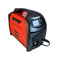
FIGURE B
SETTINGS:
· PROBE x100;
· 100 V/Div;
· 10 sec/Div.
· THE FREQUENCY
IS 35KHz ±15%;
· AMPLITUDE IS
450V ±10%;
µ
VERIFY THAT
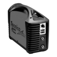
SETTINGS:
· PROBE x10;
· 10V/Div;
· 10 sec/Div.
· POSITIVE AMPLITUDE
IS +18V ±10%;
· NEGATIVE AMPLITUDE
IS -10V ±10%.
µ
VERIFY THAT
FIGURE C
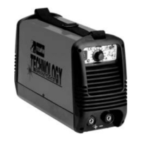
FIGURE D
SETTINGS:
· PROBE x100;
· 10V/Div;
· 10 sec/Div.
· AMPLITUDE ON
CH1 IS 35V ±20%;
µ
VERIFY THAT