I
nstallation (Continued)
Certain thermostats are supplied with a
cord and series plug for easy connection
to a 120V AC grounded receptacle. Hang
the thermostat near a 120V three prong
receptacle with a ground pin using the
hanging wire included in the package.
Plug the male prongs into the receptacle
and then plug the controlled equipment
into the female part of the plug. For best
results do not locate the thermostat near
an exterior wall or window and away
from the discharge of the equipment.
If an extension cord is required use only
one with a grounded 3 prong plug and
14 gage wire.
Do not allow the
thermostat to be
placed on the floor where it could come
in contact with moisture, or be stepped
on. Doing so could result in a fatal
electric shock.
RAINTIGHT THERMOSTAT
INSTALLATION (TP506, TP508, TP509,
TP517, TP518, TP519, TP520 & TP520B)
These thermostats are designed for use
in wet or humid environments. They meet
NEMA 4X requirements when used with
approved watertight connectors (not
included).
To ensure water tightness, a UL listed
cord seal or conduit hub marked “4X”
should be tightened onto the conduit
before installing in the enclosure. A drip
loop must be used to prevent moisture
from entering the thermostat housing.
Make certain that all connectors are
securely tightened.
When reinstalling the cover, make sure
it is squarely positioned over the gasket.
Then uniformly tighten the screws, evenly
compressing the gasket to provide a
watertight seal. Do not overtighten.
MOUNTING – EXTENDABLE BULB
THERMOSTAT INSTALLATION
(TP504, TP505, TP506, TP513,
TP514, TP516, TP519 & TP520B)
These thermostat models have a
sensor bulb attached to the end of an
extendable capillary tube. The sensor
bulb on these units is designed to monitor
temperature remotely from the control
module.
When extending the sensor, avoid
bending or kinking the extendable
capillary tube, as this will affect the
accuracy of the unit. Make sure that
any excess tubing is coiled beneath
the thermostat control module.
The control module should be located in a
c
onvenient place within a distance easily
reached by the thermostats’ extendable
sensing bulb.
Care should be taken to install the
sensing bulb where it will sense the
a
verage ambient temperature of the
area to be controlled.
F
or remote room installations, mount
the sensing bulb in a location where the
ambient air can easily circulate around
t
he sensing bulb. For cold room
installations, the sensing bulb may
also be mounted on the suction side of a
r
efrigerant line, and secured in position.
For duct installations, position the
s
ensing bulb where it is in the primary
air stream and avoid mounting the
sensing bulb close to hot pipes, cooling
coils, or other areas which may cause
an inaccurate reading.
For tank installations, the sensing
bulb can be inserted directly into the tank
fluid. Place the sensing bulb in a location
where the liquid will circulate around the
sensing bulb and where it is not affected
by extraneous temperatures. When
mounting in a tank:
• First drain the system.
• Then screw an approved boiler plug
into a pipe tapping (not supplied).
• Position a packing nut on the capillary
tubing of the sensing bulb.
• Slip the sensing bulb completely
through the boiler plug.
• Put the composition disc and slotted
brass washers on the capillary tubing.
• Slide the assembly into the boiler plug
and tighten the packing nut.
• Refill the system and check for leaks.
• Coil the excess capillary tubing, taking
care to avoid any crimps.
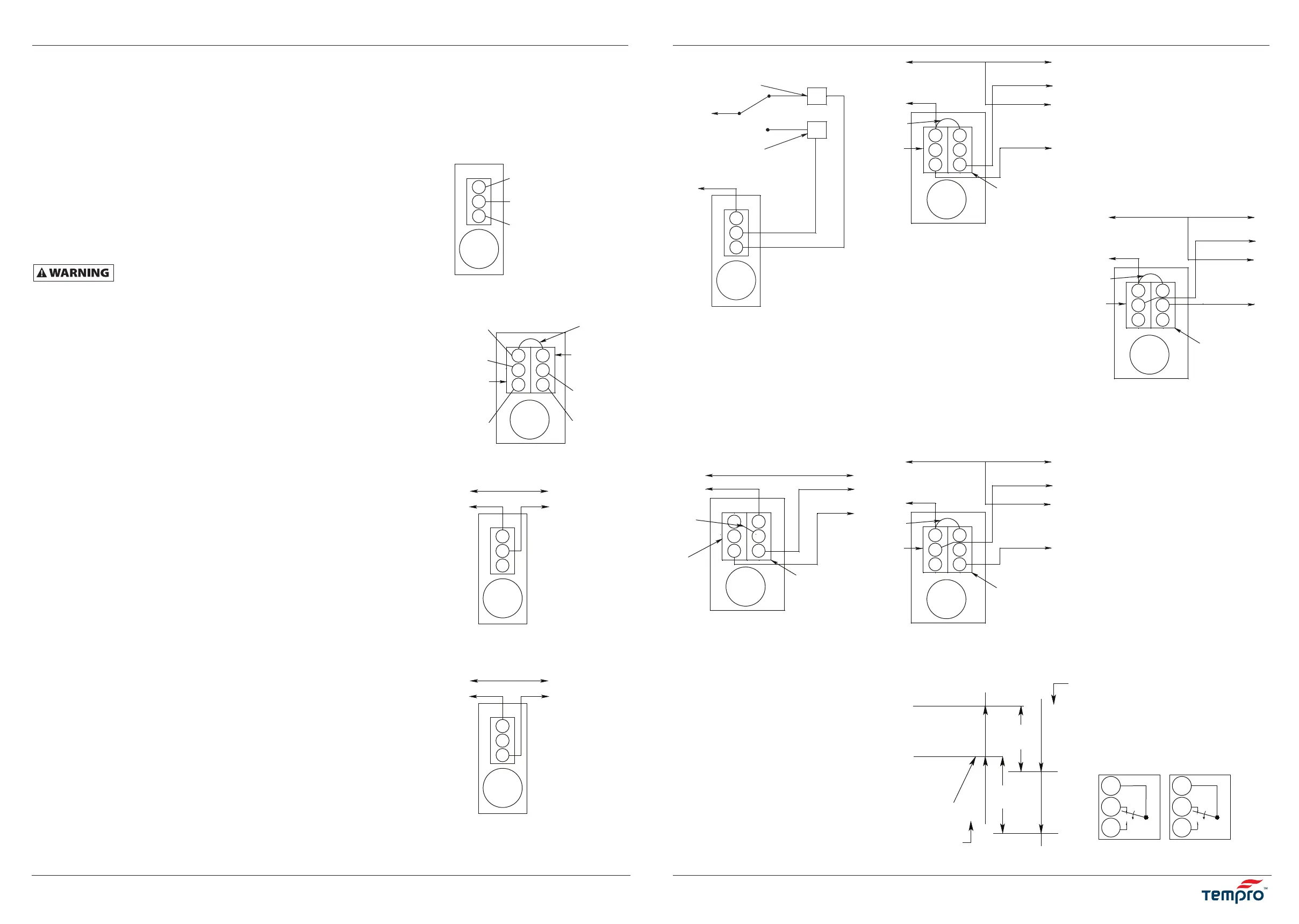
WIRING
IMPORTANT: All wiring should be
done in accordance with applicable
codes, ordinances and regulations. Use a
disconnect device and overload protection
to assure safe installation complying with
local and national codes. Figures 1, 2 and
3 illus trate typical wiring for control
of heating, cooling, refrigeration, and
combi nation heating/cooling control
systems (use copper conductors only).
NOTE 1: Letters R, B and Y (red, blue and
y
ellow) refer to color of paint dots near
terminals, or wire colors for some models
(see Figure A).
NOTE 2: For high temp stage. For models
TP520 and TP520B the high temp stage
w
ires are black for cooling and brown
for heating applications (see Figure B).
T
P500 thru TP525
3-Fr2
I
nstallation (suite)
La Figure 4 indique le câblage de commande
d’un ventilateur à deux vitesses. Lorsque
l’élément de commande atteint la température
sélectionnée par le bouton de réglage, le
contacteur de basse température démarre le
ventilateur à basse vitesse. Si la température
ambiante continue d’augmenter, le contacteur
de haute température alimente l’enroulement
du moteur haute vitesse.
La Figure 5 indique un raccordement
SPDT/SPDT (commutateur unipolaire
bidirectionnel) typique pour une application
de ventilateur à deux vitesses. Le moteur de
registre sera activé lorsque la température
atteint la température sélectionnée par le
bouton de réglage. Si la température continue
d’augmenter, le moteur du ventilateur sera
activé par le contacteur haute température.
Les appareils SPDT/SPDT peuvent également
être utilisés pour commander un dispositif
combiné de chauffage et ventilation, ou un
système de refroidissement, comme indiqué
à la Figure 6. Une température supérieure
qui dépasse la température sélectionnée
par le bouton de réglage arrête le système
de chauffage lorsque les contacts Rouge-Bleu
de basse température sont coupés. Une
augmentation de température de l’ordre de
1,7 °C (3 °F) active le ventilateur ou le système
de refroidissement par le fil Rouge-Noir ou
par les contacts point Rouge, point Jaune
du commutateur de haute température.
La Figure 7 illustre un câblage typique
pour les appareils SPDT/SPDT permettant
de commander deux étages de chauffage.
Lorsque la température ambiante baisse par
rapport à la température sélectionnée par
le bouton de réglage, le contacteur haute
température établit le contact du fil Rouge-
Marron ou des points Bleu et Jaune qui
active le premier étage de chauffage. Si la
température continue à baisser [environ 1,7 °C
(3 °F)], le contacteur basse température établit
un contact Rouge-Bleu qui active le deuxième
étage de chauffage.
PROCÉDURES DE VÉRIFICATION
Avant de quitter l’installation, observer
un cycle complet de fonctionnement pour
s’assurer que tous les composants fonctionnent
correctement. Vérifier le bon fonctionnement
dans la séquence suivante :
1. Lorsque les thermostats sont connectés
au système de réfrigération, ventilation ou
refroidissement : Tourner le bouton dans le
sens horaire à un réglage supérieur à celui
de la température ambiante. Le système de
ventilation ou de refroidissement doit être
désactivé. Lorsque le bouton est tourné
dans le sens antihoraire (un réglage de
température inférieure), le ventilateur ou
le système de refroidissement doit s'activer
aux environs du réglage du bouton.
Alimentation électrique
(C) Commun
Système de chauffage
Ventilateur soufflant
ou système de
refroidissement
Figure 3 – Thermostats SPDT dans les
systèmes de commande de
chauffage et de ventilation
Alimentation électrique
(C) Commun
Vers le moteur
du ventilateur
Voir la
REMARQUE 2
et la Figure B
dans la section
CÂBLAGE
Figure 4 – Thermostats SPDT/SPDT à deux
étages de commande d’un
ventilateur à deux vitesses
Basse
temp.
Haute vitesse
Basse
vitesse
Cavalier
Alimentation électrique
(C) Commun
Vers le moteur
du ventilateur
Voir la
REMARQUE 2
et la Figure B
dans la section
CÂBLAGE
Figure 5 – Thermostats SPDT/SPDT à deux
étages contrôlant un ventilateur
à vitesse unique et un moteur
de registre à augmentation
de volume
Basse
temp.
Cavalier
Vers le moteur
de registre ou
deuxième moteur
de ventilateur
Alimentation électrique
(C) Commun
Vers le moteur
chauffant ou
le système
Voir la
REMARQUE 2
et la Figure B
dans la section
CÂBLAGE
Figure 6 – Thermostats SPDT/SPDT avec
transfert automatique entre
les modes de commande des
systèmes de chauffage et
de refroidissement
Basse
temp.
Cavalier
Vers le système de
ventilation ou de
refroidissement
Alimentation électrique
(C) Commun
Vers le deuxième
étage de chauffage
Voir la
REMARQUE 2
et la Figure B
dans la section
CÂBLAGE
Figure 7 – Thermostats SPDT/SPDT
contrôlant un système de
chauffage à deux étages
Basse
temp.
Cavalier
Vers le premier
étage de
chauffage
Figure 8 – Séquence de fonctionnement des thermostats SPDT/SPDT à deux étages
Basse temp.
Haute temp.
Baisse de temp.
RB bas
se ferme
Étage
inférieur
RY bas
s’ouvre
RB élevé
se ferme
RY élevé
s’ouvre
Étage
supérieur
RY élevé
se ferme
RB élevé
s’ouvre
RY bas
se ferme
RB bas
s’ouvre
Réglage de temp.
Hausse de temp.
T
P500 à TP525
Power Supply
(C) Common
To heating
system
B open on
temp. rise
Figure 1 – Connection for a Typical
Heating Control Circuit
Power Supply
(C) Common
To fan motor or
refrigeration unit
Y close on
temp. rise
Figure 2 – Connection for a Typical
Refrigeration, Ventilation
or Cooling Control Circuit
Adjust
knob
Adjust
knob
NOTE: Terminal
B is not used on
SPDT models.
©Kamal International
Bowling Green, KY 42101
©Kamal International
Bowling Green, KY 42101
Red Dot or Wire (Power)
Figure A
Adjust
knob
Figure B
Adjust
knob
Low temp.
switch
control
J
umper
Blue Dot or Wire (Heat)
Yellow Dot or Wire (Cool)
High temp.
switch
control
Red Dot
or Wire
(Power)
Blue Dot
or Wire
(Heat)
Yellow Dot
or Wire
(Cool)
Blue Dot
or Black
Wire (Heat)
Yellow Dot
or Brown
Wire (Cool)
Bouton
de
réglage
Bouton
de
réglage
Bouton
de
réglage
Bouton
de
réglage
Bouton
de
réglage
 Loading...