14 |
TS35
03 TECHNICAL
INSTRUCTIONS
TS35-U06 / Rev. 00 / 22.06.12
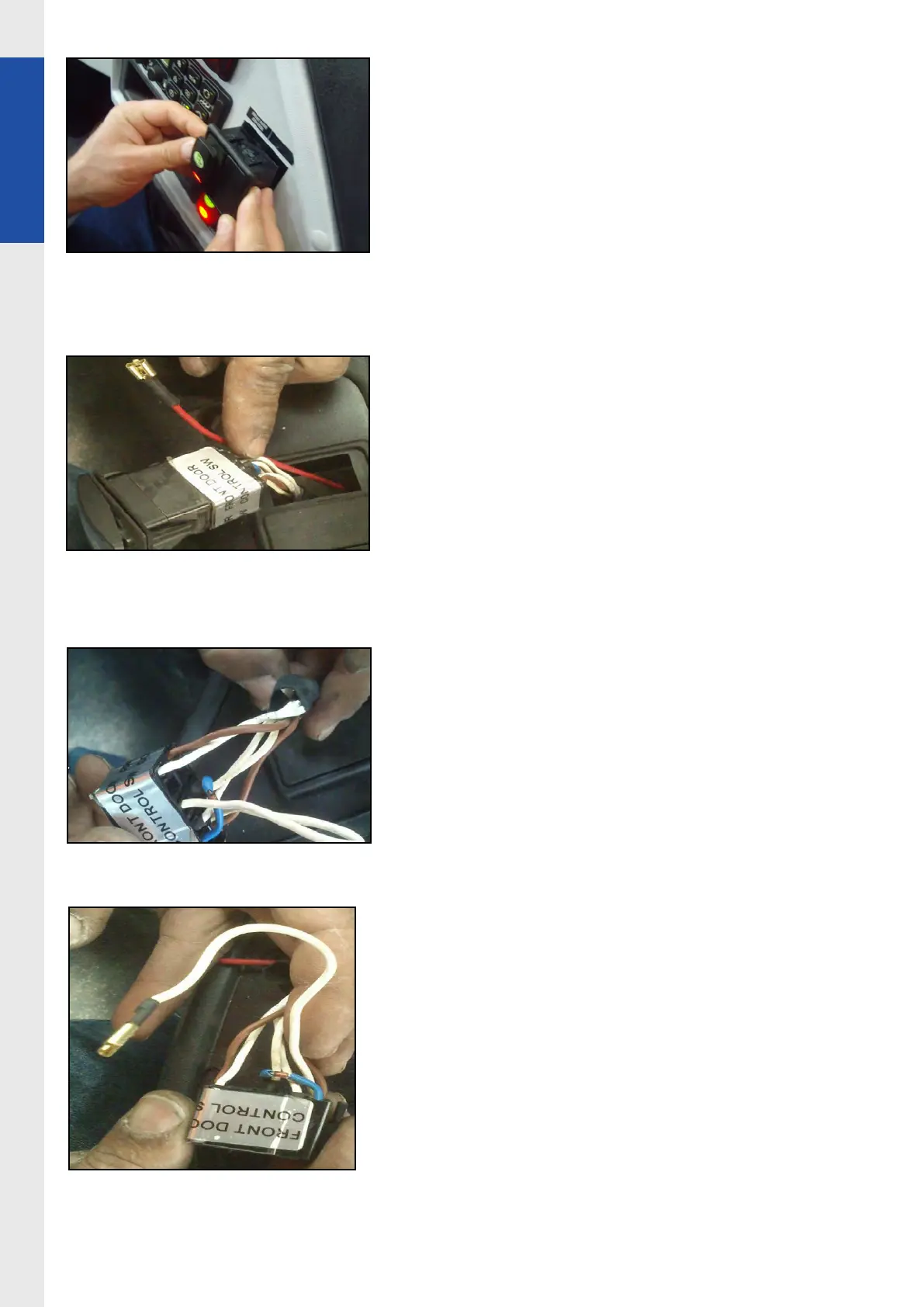
Photo 24
Photo 25
9.Move other side of 13-01 to door control
switch to make necessary connection
(other side of the 13-01 is in the modication
harness 13-01 is rst used in step-4 and step5)
Photo 26
10.Dismantle and isolate white cable which is
available in 2nd pin of hazard switch connect
13-01 (instep-7) to this pin
(2nd pin of hazard switch)
Photo 27