TS35
|
15
03 TECHNICAL
INSTRUCTIONS
TS35-U06 / Rev. 00 / 22.06.12
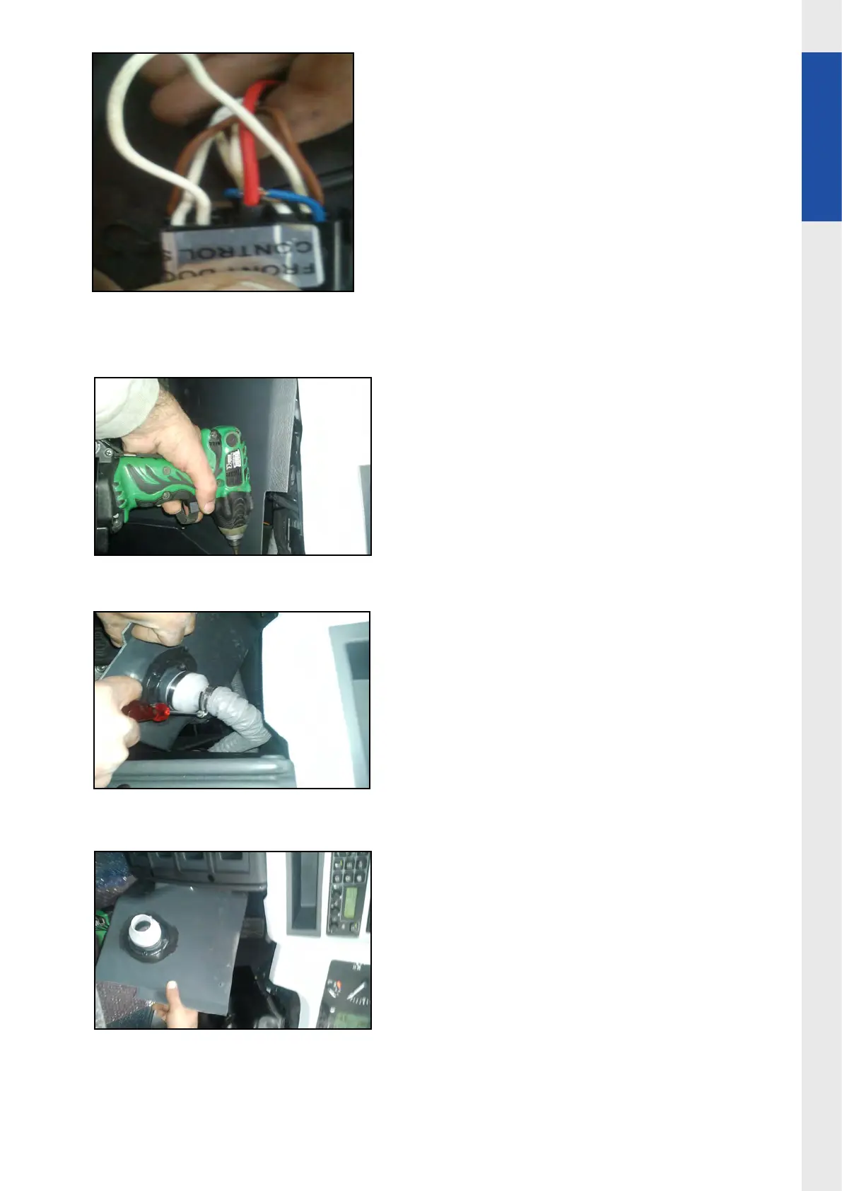
9.Move other side of 13-01 to door control
switch to make necessary connection
(other side of the 13-01 is in the modication
harness 13-01 is rst used in step-4 and step5)
10.Dismantle and isolate white cable which is
available in 2nd pin of hazard switch connect
13-01 (instep-7) to this pin
(2nd pin of hazard switch)
Photo 28
11.Dismantle MOKI D connector from rear side
of MOKI to reach and dismantle moki connector
rst dismantle cover just above throttle pedal
as shown pictures.
Photo 29
Photo 30
Photo 31