Do you have a question about the Tenma 72-2535 and is the answer not in the manual?
Details AC input voltage, frequency, and grounding conductor connection for safe operation.
Specifies environmental conditions for optimal operation, including location, humidity, and temperature.
Outlines recommended conditions for storing the power supply when not in use.
Highlights key performance aspects like low noise cooling and compact size.
Details constant voltage/current modes, output control, panel control, and setup save/recall.
Lists overload, reverse polarity, and short circuit protection mechanisms.
Describes USB/RS232 remote control capabilities for specific models.
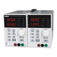
Explains the voltage and current level indicators on the front panel display.
Details OVP, OCP, CC, CV, and OUT indicators and their meanings.
Describes M1-M5 indicators for saving and recalling panel setups.
Explains saving and recalling panel settings using M1-M4 buttons.
Details how to adjust voltage and current using the adjustment knob and digit selector buttons.
Describes the procedure for turning the power supply on and off using the power switch.
Details how to turn the output on and off using the dedicated key and indicator.
Explains how to enable or disable the beep sound by pressing the OCP key.
Describes how to lock and unlock the front panel controls to prevent accidental changes.
Details connecting load, switching voltage/current, adjusting values, and selecting coarse/fine mode.
Explains how to save current panel settings into one of the four internal memories (M1-M4).
Details how to recall stored panel settings from memory using M1-M4 buttons.
Specifies Baud rate, Parity, Data bits, Stop bit, and Flow control for remote connection.
Describes how to run a query command to verify the connection and retrieve identification information.
Details connecting the USB, automatic connection, and panel key lock upon entering remote mode.
Explains how to close software, disconnect USB, and return to panel control mode.
Defines the structure of commands including VSET header, output channel, and parameter format.
Details commands for setting (ISET) and querying (ISET?) output current.
Details commands for setting (VSET) and querying (VSET?) output voltage.
Commands to query the actual output current (IOUT?) and voltage (VOUT?).
Commands for beep control (BEEP), output control (OUT), and status query (STATUS?).
Explains the meaning of each bit in the POWER SUPPLY status response.
Commands for beep (BEEP), lock (LOCK), and output (OUT) state management.
Command (*IDN?) to retrieve the power supply identification information.
Command (RCL<NR1>) to recall panel settings stored in memory.
Command (SAV<NR1>) to store current panel settings into memory.
Commands to control Over-Current Protection (OCP) and Over-Voltage Protection (OVP).
Details the voltage and current range specifications for each part number.
Specifies the load regulation for voltage and current across different models.
Details the line regulation specifications for voltage and current.
Indicates the voltage and current resolution for setup.
Specifies the setup accuracy for voltage and current at different temperatures.
Details the voltage and current ripple specifications (20-20m).
Provides temperature coefficient values for voltage and current.
Specifies read back accuracy, temperature coefficient, and reaction time for voltage and current.
Lists available interfaces (RS232, USB) and included accessories (manual, power cord).
Details the physical dimensions and weight for different part numbers.
The Tenma Digital-Control and Programmable DC Power Supply is a versatile and robust instrument designed for a wide range of electronic testing and development applications. This device offers precise control over voltage and current output, making it suitable for tasks requiring stable and adjustable power. Its digital interface and programmable features enhance usability and allow for automated testing scenarios.
At its core, the Tenma power supply provides a regulated DC voltage and current output. Users can precisely set both the output voltage and current limits through a digital panel, ensuring that connected circuits receive the exact power required. The device operates in both constant voltage (CV) and constant current (CC) modes, automatically switching between them based on the load conditions. In CV mode, the output voltage remains constant while the current varies to meet the load's demands, up to the set current limit. Conversely, in CC mode, the output current is held constant, and the voltage adjusts to maintain that current, up to the set voltage limit.
A key feature of this power supply is its programmability. It allows users to store and recall multiple panel settings, facilitating quick setup for recurring tests or different circuit configurations. This memory function is particularly useful in environments where various projects or test routines are frequently performed. The device also includes an output on/off control, enabling users to safely connect or disconnect loads without having to power down the entire unit.
Safety is a paramount consideration in the design of the Tenma power supply. It incorporates several protection mechanisms, including overvoltage protection (OVP), overcurrent protection (OCP), overload protection, reverse polarity protection, and short circuit protection. These features safeguard both the power supply and the connected device from potential damage due to unexpected conditions or incorrect connections. For instance, if the output voltage exceeds a preset OVP limit, the output will automatically cut off, and an indicator will alert the user. Similarly, OCP prevents excessive current from flowing through the circuit.
The device also supports remote control capabilities via USB or RS232 interfaces, allowing it to be integrated into automated test systems or controlled from a computer. This functionality is invaluable for complex experiments, data logging, or situations where manual operation is impractical or undesirable. The remote control interface enables users to set voltage and current, monitor output, and manage protection settings programmatically.
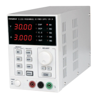
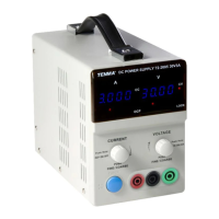
The Tenma power supply is designed for intuitive and efficient operation. The front panel features a clear digital display that shows both the set and actual output voltage and current values, providing real-time feedback to the user. The display also includes indicators for various operational states, such as OVP, OCP, CV mode, CC mode, and output status, ensuring that users are always aware of the device's current condition.
Voltage and current adjustments are made using a combination of a rapid adjustment knob and coarse/fine adjustment buttons. This allows for both quick, large changes and precise, granular adjustments, catering to different levels of accuracy required for various applications. Digit selector buttons further enhance precision by allowing users to select specific digits for adjustment, making it easier to dial in exact values.
The memory function is a significant convenience feature. Users can save up to four distinct panel settings (M1-M4), which include the fine/coarse knob editing mode, beep on/off status, and output voltage/current levels. These settings can be recalled instantly, saving time and reducing the potential for errors when switching between different test configurations. The device also automatically saves the last used settings, ensuring that it powers up in a familiar state.
An output on/off button provides immediate control over the power delivery to the load. This is crucial for safely connecting or disconnecting components, preventing accidental power surges, or quickly cutting power in an emergency. The key LED associated with this button clearly indicates whether the output is active.
For environments where audible feedback is desired or needs to be suppressed, the device includes a configurable beep function. Users can easily toggle the beep sound on or off by pressing and holding the OCP (BEEP) key for a few seconds. This small but thoughtful feature enhances user comfort and adaptability to different working conditions.
The front panel lock-out function adds another layer of control, preventing accidental changes to settings during operation. When activated, this feature disables the front panel keys, ensuring that the power supply maintains its configured output without interruption. This is particularly useful in long-duration tests or in shared lab environments.
Remote control capabilities extend the usability of the power supply beyond manual operation. By connecting to a computer via USB or RS232, users can control all aspects of the device through software. This enables automated testing sequences, data logging, and integration into larger control systems, making the power supply a powerful tool for research, development, and production testing. The device automatically enters remote control mode upon connection and provides a clear audible signal when entering or exiting this mode.
The Tenma power supply is designed for reliability and ease of maintenance, focusing on user safety and operational longevity. The device features a cooling fan, which is controlled by the heatsink temperature. This intelligent cooling system ensures efficient heat dissipation, preventing overheating and contributing to the stability and lifespan of the internal components. The fan's operation is optimized to minimize noise while effectively maintaining optimal operating temperatures.
Fuse replacement is a straightforward process, with clear instructions provided in the manual. The fuse parameters are specified on the back label of the device, indicating the correct type and rating for both 110V/120V and 220V/230V AC input voltages. Users are explicitly warned to disconnect power before replacing the fuse and to ensure that the cause of any fuse blowout is addressed to prevent recurrence. This attention to detail in maintenance instructions helps users safely and correctly service the unit.
The power supply is built with robust protection features that also contribute to its maintenance by preventing damage. Overvoltage, overcurrent, overload, reverse polarity, and short circuit protections are integral to the device's design. These features not only protect connected loads but also shield the power supply's internal circuitry from potentially damaging conditions, thereby reducing the need for repairs and extending its operational life.
Software calibration is another maintenance-related feature, allowing for precise adjustments to maintain accuracy over time. This ensures that the voltage and current readings and outputs remain within specified tolerances, which is critical for applications requiring high precision.
The device's compact size and light weight contribute to its ease of handling and placement in various work environments. This physical design simplifies installation and relocation, making it a practical choice for labs or workshops with limited space.
The overall construction emphasizes durability, with warnings against severe impacts or rough handling to prevent damage. This guidance encourages proper care of the instrument, which is a fundamental aspect of maintenance. The instruction to avoid static electricity discharge also highlights best practices for handling sensitive electronic equipment, further contributing to the device's longevity.
In summary, the Tenma Digital-Control and Programmable DC Power Supply combines precise control, extensive safety features, and user-friendly operation with robust construction and straightforward maintenance guidelines. Its ability to store settings, operate remotely, and protect against various electrical faults makes it a highly capable and reliable tool for a wide array of electronic applications.
| Output Voltage | 0-30V |
|---|---|
| Output Current | 0-5A |
| Power Rating | 150W |
| Ripple and Noise | ≤1mVrms |
| Weight | 4.5kg |
| Cooling | Fan |
| Frequency | 50/60Hz |
| Input Voltage | 220V ±10%, 50/60Hz |
| Protections | Over Voltage, Over Current, Over Temperature |
| Operating Temperature | 0 to 40 °C |
| Storage Temperature | -20 to 70 °C |
| Voltage Regulation | ≤0.01% + 3mV |