EasyManua.ls Logo

Tenma 72-10495 User Manual

Tenma 72-10495
11 pages
To Next Page IconTo Next Page
Page #1 background imageLoading...
Page #1 background image
Important notes to avoid damage:
- Do not allow power supply to sink current. (Use diode when charging battery.)
- In series mode, the voltage at the output is the sum of the voltages on the CH1 and CH2
displays
- In parallel mode, the current at the output is the sum of the currents on the CH1 and CH2
displays
- In parallel mode, connect load to CH2 (right hand) channel. (When mains power is turned
on, the power supply defaults to independent mode, and CH1 to whatever voltage and cur-
rent settings are in CH1 memory recall M1, with the load turned off.)
- OCP and OVP do not work in serial and parallel modes.
- For sensitive circuits, disconnect load before:
- Switching load on or off with “OFF/ON” button for that channel
- Switching mains off with the load switched on
Do not leave a load connected to CH2 in SER (serial) mode. If you recall a CH2 memory in
SER mode, only CH2 is updated from that memory and only CH2 turns off. At this time, CH2
output terminals have up to -1.2 V (i.e. reverse polarity) on them, with a short circuit current
of up to -2.8 A.
Important notes to avoid frustration:
- Automatically switches between constant voltage (CV) and constant current (CC) modes
- There is a small +/- voltage and current while the load is switched off (50mV, 100 uA)
- CH2 OUT LED stays on after CH2 OCP/OVP trip disconnects the load.
- CH2 OVP/OCP buttons also control CH1 OVP/OCP
- CH1 OVP/OCP buttons only control CH1 OVP/OCP
- The OCP and OVP LEDs apply to whichever channel last updated them. Pressing either
the OVP or OCP buttons updates both the OVP and OCP LEDs with current state for that
channel.
Edits are in colour, and from an end user who has no affiliation with the supplier or manufac-
turer. No liability is accepted for any information in, or omission from, this document. Your
unit may work differently than described here if it has a different hardware or software ver-
sion.
Use at your own risk
- TENMA 72-10495 (Korad KA3005D-2S): 30V-5A x 2 Channels
- TENMA 72-10500 (Korad KA3003D-2S): 30V-3A x 2 Channels
- TENMA 72-10505 (Korad KA3003D-3S): 30V-3A x 2 Channels & 5V-3A x 1
Velleman supply the single channel version with remote interface as the Velleman LABPS3005D
(which they used to call the PS3005D) The "D" in the Korad model number means no remote in-
terface.

Other manuals for Tenma 72-10495

Question and Answer IconNeed help?

Do you have a question about the Tenma 72-10495 and is the answer not in the manual?

Tenma 72-10495 Specifications

General IconGeneral
BrandTenma
Model72-10495
CategoryPower Supply
LanguageEnglish

Summary

Power Supply Damage Prevention

Critical Safety Measures for Damage Avoidance

Key precautions to prevent damage to the power supply unit during operation, like avoiding current sinking.

Operational Notes for User Experience

Tips for Smooth Operation and Indicator Behavior

Guidance on common operational modes, indicator functions, and LED behavior to prevent user frustration.

Safety Symbols and Warnings

Understanding Safety Icons

Detailed explanation of safety symbols like WARNING, DANGER High Voltage, and Earth Terminal.

Safety Guidelines and Environment

Operational and Storage Environment Conditions

Specifies ideal conditions for operation and storage, including humidity and temperature.

AC Input and Fuse Replacement

Details AC input voltage compatibility and fuse replacement guidelines.

Product Lineup and Main Features

Model Specifications and Resolution

Table outlining voltage, current meter, and resolution for each model.

Key Performance and Operation Features

Lists main features like low noise, CV/CC operation, and protection mechanisms.

Front Panel Overview and Controls

Front Panel Component Identification

Detailed diagram and explanation of front panel controls and indicators.

Display Indicators and Status

Voltage, Current, and Condition Displays

Explains how voltage, current, and operational status indicators are displayed.

Storage and Recall Indication

Details the meaning of storage status indicators.

Panel Operation Functions

Memory, Lock, and Beep Functions

Explains saving/recalling settings, panel lock, and beep control functionality.

Voltage/Current Adjustment and Power Control

Describes how to adjust voltage/current and the main power control.

Basic Power Supply Operations

Connecting Power and Output Control

Steps for connecting AC power and controlling the output ON/OFF state.

Beep Functionality and Behavior

How to enable or disable the unit's beep sound and its operational behavior.

Series and Parallel Operation Modes

Series Mode Operation and Limitations

How to operate the supply in series mode, including connections and limitations.

Parallel Mode Operation and Limitations

How to operate the supply in parallel mode, including connections and limitations.

Output Set and Configuration

Setting Output Voltage and Current

Steps for setting desired output voltage and current levels.

Setup Saving and Recalling

Saving Panel Configurations

Explains how to save panel settings into internal memories.

Recalling Saved Panel Settings

Details how to retrieve stored panel settings from internal memory.

Front Panel Lock and Recall

Locking and Unlocking Panel Controls

How to activate and deactivate the front panel lock function.

Recalling Stored Settings

Procedure for retrieving stored panel settings from internal memory.

Frequently Asked Questions (FAQ)

Troubleshooting Common Operational Issues

Addresses common problems like unresponsive buttons, no output, and LED behavior.

Technical Specifications

Model Performance and Electrical Specifications

Comprehensive list of electrical and performance specs for each model.

Accuracy, Ripple, and Accessories

Details accuracy, ripple, temperature coefficients, and supplied accessories.

Calibration Procedures

Zero and Full-Range Calibration Steps

Step-by-step guide for calibrating voltage and current zero and full-range settings.

Required Instruments and Conditions

Lists required instruments and pre-calibration conditions.
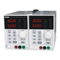
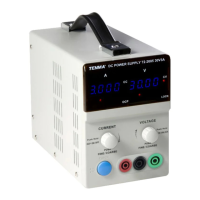
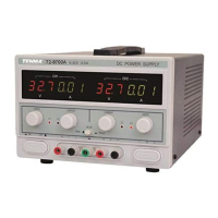
Related product manuals