EasyManua.ls Logo

Tense DT-96 User Manual

Tense DT-96
4 pages
To Next Page IconTo Next Page
Page #1 background imageLoading...
Page #1 background image
TENSE Elektronik
1
DT-96 / DT-72 / DT-48
AUTO-TUNE PID TEMPERATURE CONTROLLER
General Specification:
µP based, PID temperature controller with OUT and ALARM outputs
Auto-tuning for PID parameters
Sensor type: T/C (J,K,T,S,R), Pt100, selectable, multi-input
Selectable control type: P, PI, PD, PID or ON-OFF
Automatic “Overshoot” elimination in PID mode
“Anti-windup”
Upper and Lower limit for SET and ALARM settings
Selectable relative, absolute or band alarm
ON-delay for OUT in cooling mode
Displays SET and PROCESS values
Cold-junction compensation for T/C
Line compensation for Pt100
Excellent linearity with
o
C/mV and
o
C/ look-up tables
Input “Offset” feature
Password protection
High accuracy
EEPROM memory to store settings
Optional SSR output
Easy connection with plug-in connectors
CONNECTION
no: normally open
nc: normally closed
Warning: if 2 wire Pt100 is used, connect
compansation lead to measuring lead
(DT-96: 17-18,DT-72: 13-14,
DT-48: 10-11)
1
2
3 10
4 11
5 12
6
7
Out
Alarm
no
nc
+
100 ... 240VAC
50/60Hz 6VA
Out & Alarm;
250V max.2A
resistive load
AC
T/C
Pt100
Out & Alarm;
250VAC
max. 2A
resistive load
17
18
19
T/C
Pt100
3
4
5
8
6
9
7
10
Out
Alarm
no
no
nc
nc
100 ... 240VAC
50/60Hz 6VA
13
14
15
T/C
Pt100
+
Out & Alarm:
250V max.2A
resistive load
AC
3
4
5
8
6
9
7
10
Out
Alarm
no
no
nc
nc
100 ... 240VAC
50/60Hz 6VA

Other manuals for Tense DT-96

Question and Answer IconNeed help?

Do you have a question about the Tense DT-96 and is the answer not in the manual?

Tense DT-96 Specifications

General IconGeneral
BrandTense
ModelDT-96
CategoryController
LanguageEnglish

Summary

General Specification

Connection

Technical Specification

Programming Parameters

Input Sensor Type

Selectable sensor input types including T/C and Pt100.

Heating/Cooling Function

Selectable heating or cooling control mode for the device.

Hysteresis Settings

Configuration of hysteresis for heating and alarm functions.

Proportional Band

Sets the proportional band width in degrees Celsius.

Control Period

Defines the control loop cycle time in seconds.

Integral and Derivative Time

Configuration of integral (Ti) and derivative (Td) times for PID control.

Alarm Limits

Setting upper (UP.L) and lower (Lo.L) limits for alarms.

Offset Adjustment

Allows direct addition of an offset value to the measured value.

Alarm Type Selection

Choice of alarm modes: absolute, relative, or band.

Relative/Band Alarm Value

Sets the value for relative or band alarm modes.

Cooling Delay Timer

Minimum delay before OUT turns ON in cooling mode.

Failure Output Control

Determines OUT behavior when a 'Fail' message is displayed.

Programming Heat SET and Absolute Alarm SET

Heat SET Configuration

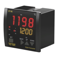
Setting the target temperature (Process SET) for heating.

Absolute Alarm SET Configuration

Setting absolute alarm limits, displayed if Ab.AL=Yes.

Alarm Output Logic

Defines the logic for different alarm output types (Abs, Rel, Bnd).

Output Control (ON-OFF)

ON-OFF control is active when 'H.Hys' is set to a value other than 0.

PID Control Parameters

Details on PID, Proportional Band (PbC), Integral (Ti), and Derivative (Td) times.

Related product manuals