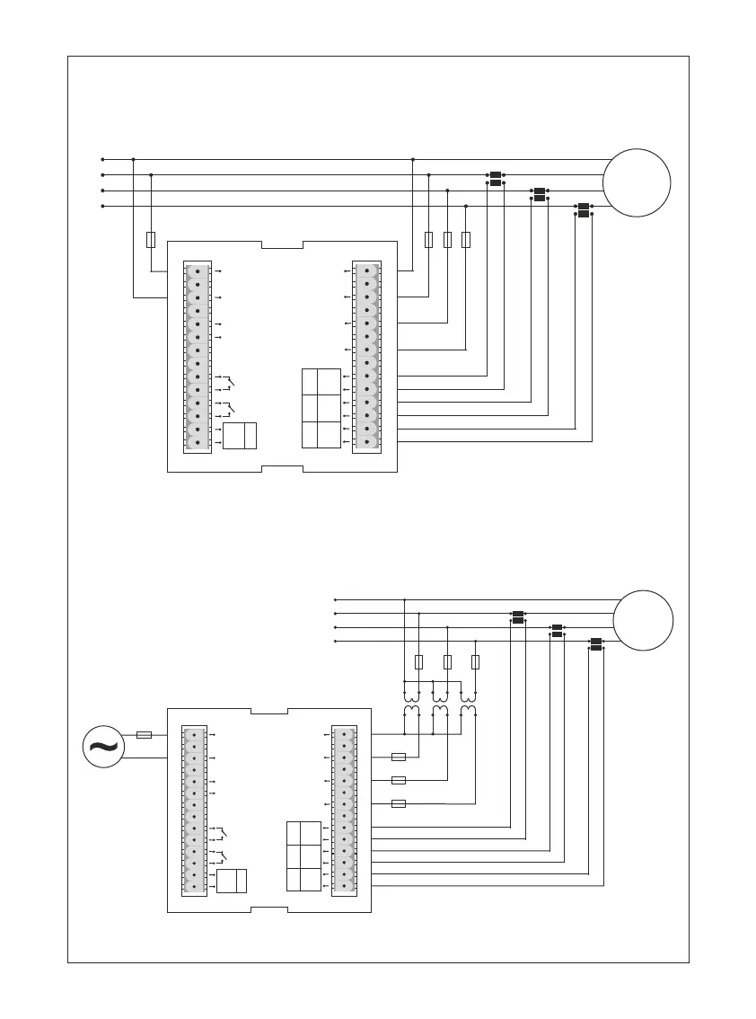
Figure-1: Connection Type of 3P4W: 3 Phase current and 3 phase voltage. Neutrality.
Figure-2: 3 Phase current and 3 phase voltage. Neutrality.
It is suitable for medium voltage with voltage transformer.
1 - Connection Diagrams:
-1-
N
2A
L1
L2
L3
Load
Figure-1
18
17
16
15
19
20
21
22
23
24
25
3
2
1
26
27
28
4
5
6
7
8
9
10
11
12
14
13
A1
A2
N
L1
L2
L3
Max. 5A AC
I1I2
I3
I3
k3
I2
k2
I1
k1
Ct3
S1
P1
S2
P2
Ct2
S1
P1
S2
P2
Ct1
S1
P1
S2
P2
RS485
A
B
DIN+
DIN-
Out1
Out2
N
2A
L1
L2
L3
Load
Figure-2
18
17
16
15
19
20
21
22
23
24
25
3
2
1
26
27
28
4
5
6
7
8
9
10
11
12
14
13
A1
A2
N
L1
L2
L3
Max. 5A AC
I1I2
I3
I3
k3
I2
k2
I1
k1
2A
V.T.1
V.T.2
V.T.3
220V AC
50/60Hz.
Ct3
S1
P1
S2
P2
Ct2
S1
P1
S2
P2
Ct1
S1
P1
S2
P2
RS485
A
B
DIN+
DIN-
Out1
Out2
2 - Matters to be considered in current transformer selection and connection
To avoid the complexity when connecting the current transformer output terminal use different colour
cables or give cable numbers.
Please spread the cables which are connected to current transformer output terminal from remote
high voltage lines.
Please fix current transformers to bara, cable or rail to avoid rattling.
Note that the value of current transformer is higher than the maximum current drawn from the system.
It is advisible that the class of the current transformer (it can be written class, klas, cl, kl) is 0.5.
3 - Warnings:
Please use the device properly according to our directions.
Please protect LCD screen from sun light.
Please take 5 cm. space behind the device after the device installation.
Please fix the device front cover panel with the apparatus that comes with it.
Please not use device in the damp board.
Please keep key or circuit breaker close the device or in an easily accessible location by the operator.
Please add a key or circuit breaker to assembly.
There should be no electricity in the connection cables when assembling device.
There should be used shielded or twisted cord cable at the non-network-connected input and output.
lines. These cables should not be passed near the high power lines and the device.
Assembling and electrical connections must be done by technical staff according to instruction manuel.
The feed cables should be suitable for IEC 60227 or IEC 60245 requirements.
Please read the warnings before powering the device. Make connections of the device according to the
connection scheme. When the device is first powered up figure-3 displayed on the screen. Firstly enter the
current transformer ratio from the settings menu and if the voltage transformer medium voltage is being
measured), enter the voltage transformer ratios.
6 - First Operation of the Device:
5 - General:
TPM-04 Energy analyzer measures load or voltage, current, cosφ, active power, reactive power, minimum
and maximum values of the load and also measures demands. This analyzer measures current harmonics
and voltage harmonics up to 31. harmonics.
4 - Device Maintenance :
Turn off energy of the device and disconnect from connections. Clean the device body by using slightly
moist or dry cloth. Do not use conductor or other chemical as a cleaning agent matter which is harmful to
device. Make connections after the cleaning of device and give energy to device and make sure that device
works properly.
-2-
 Loading...