3-6
3.6.2. Alignment of direct type shaft coupling
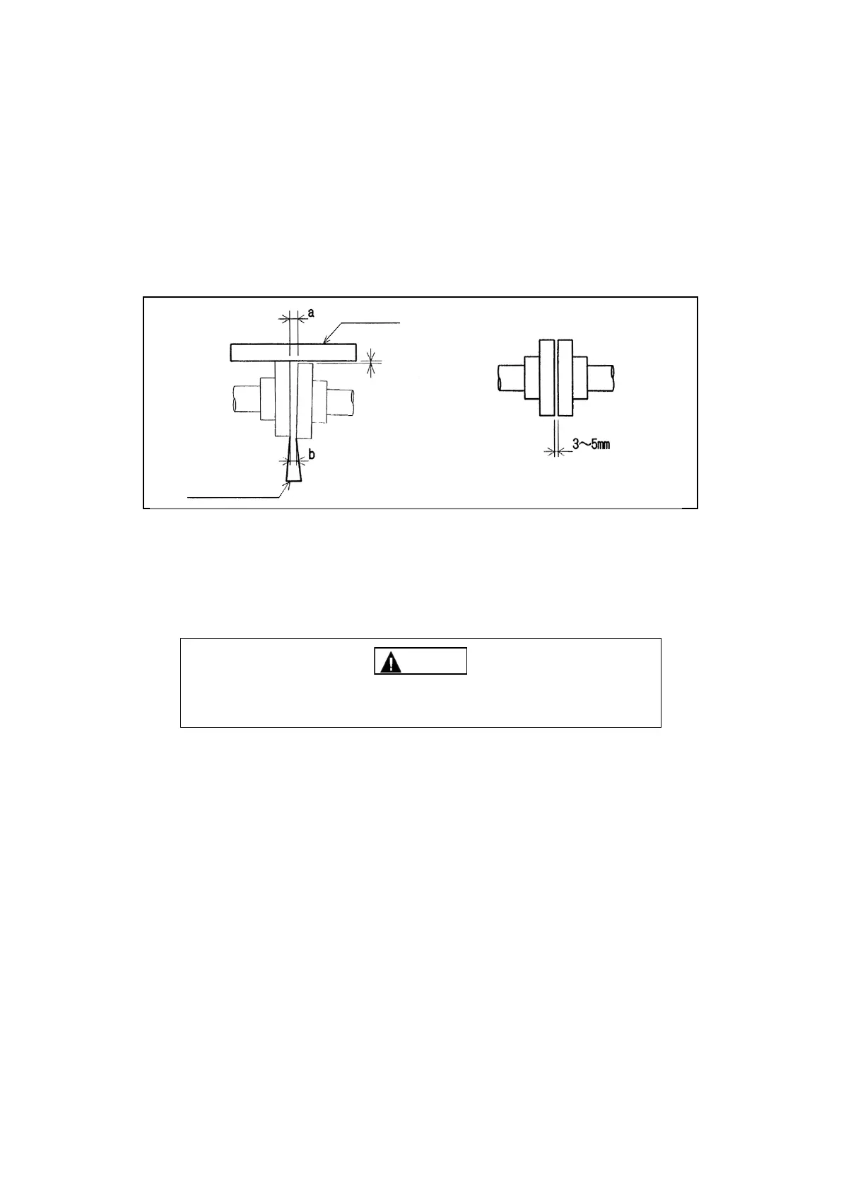
The following is an example of the case a flange type flexible shaft coupling is used.
(1) Put a parallel ruler at four places on the circumference of the shaft coupling and check the
gap between levels of the circumferences.
(2) Measure the clearance between the mating surfaces of the shaft coupling using a taper
gauge or a feeler gauge.
The tolerances are within 0.05 mm for the gap between the levels and within 0.1 mm for the
unevenness of the clearance.
Correct the alignment by inserting a shim under the motor.
Use a dial gage for the adjustment of a spring coupling or the like which requires preciseness.
3.7 Precautions for connecting the ducts
Caution
Ensure that the ducts do not apply any load to the fan.
Otherwise, malfunctions, damage or vibration may occur.
(1) Connect the fan’s flanges and ducts using expansion joints to avoid the transmission of
vibrations or noise to the exterior.
In particular, when handling a high temperature gas, be sure to install expansion joints so
that the reaction force from the duct due to thermal expansion will not be applied to the fan.
(2) Before connecting the ducts, check the inside of the ducts and fan, and remove any foreign
matters, such as waste cloth and tools.
(3) Please note that, in general, the use of ducts of which diameter is much smaller than the port
diameter of the fan, ducts with bends in series, or ducts with bends just before or after the
connection to the fan may cause an unexpected increase in pressure loss.
Parallel ruler
Within 0.05mm
Taper gauge
“a-b” should be within 0.1 mm