3-5
3.2.4 Control board
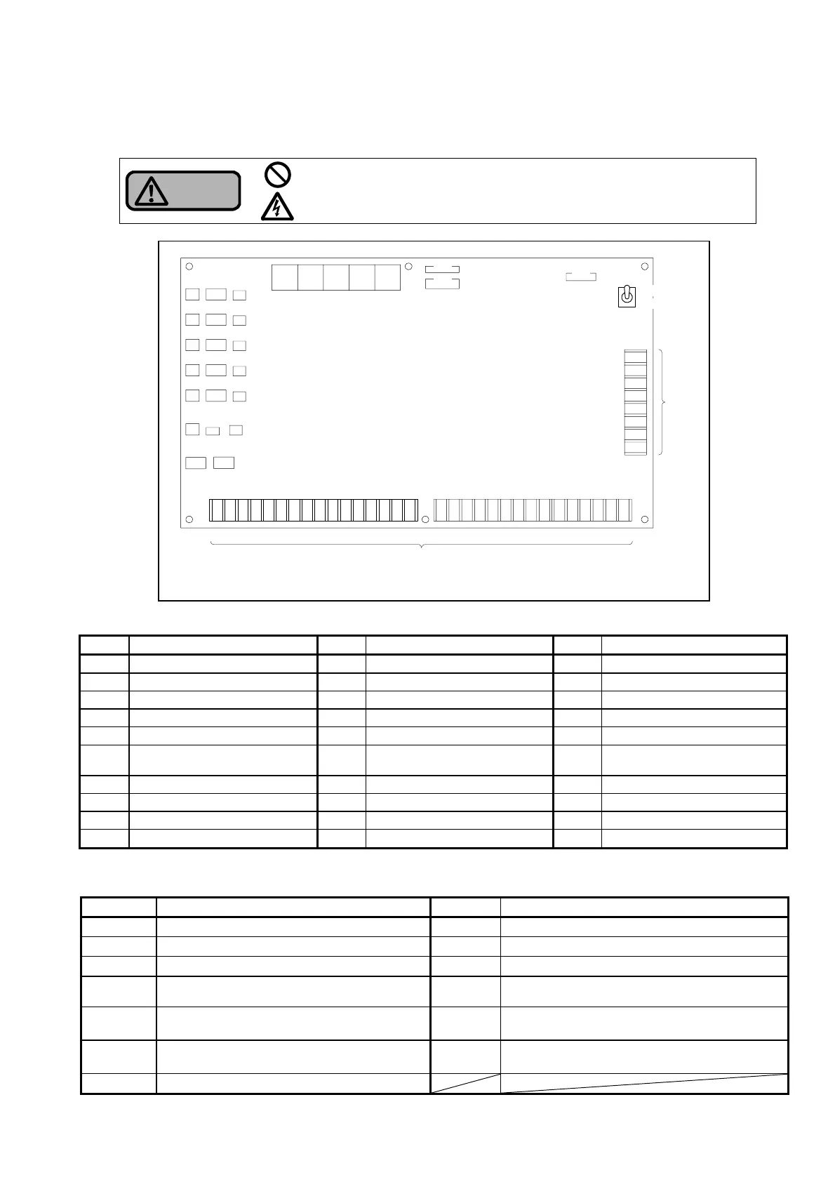
The following are the details of the control board.
Warning
Do not remove the protective cover on the control board or the cover of
the I/O terminal block when the power is turned on.
Otherwise, it may lead to an electric shock.
Table 3-2-4 (a) Connector assignments
No. Connection point No. Connection point No. Connection point
CN1
Equipment inside the control panel
CN11
Flow switch for pump No. 4
CN21
Equipment inside the control panel
CN2
Equipment inside the control panel
CN12
Flow switch for pump No. 5
CN22
Equipment inside the control panel
CN3
Equipment inside the control panel
CN13
(Unused)
CN23
Equipment inside the control panel
CN4
Equipment inside the control panel
CN14
(Unused)
CN24
Equipment inside the control panel
CN5
Equipment inside the control panel
CN15
(Unused)
CN25
Equipment inside the control panel
CN6
Control panel high-temperature
sensor
*1
CN16 High temperature sensor No. 1 CN26
Equipment inside the control panel
CN7
Pressure transmitter
CN17 High temperature sensor No. 2 CN27
(Unused)
CN8
Flow switch for pump No. 1
CN18 High temperature sensor No. 3 CN29
Equipment inside the control panel
CN9
Flow switch for pump No. 2
CN19 High temperature sensor No. 4
CN10
Flow switch for pump No. 3
CN20 High temperature sensor No. 5
*1 For models fitted with outdoor cover, this sensor is connected depending on the specifications.
Table 3-2-4 (b) Codes and application of input/output terminal block
Code Application Code Application
IL1 and IL2
Interlocking signal B1 to B8 Alarm signal output
1E0 to 1E4
Receiver tank water level detector electrode No. 1
BC Alarm signal output common
2E0 to 2E4
Receiver tank water level detector electrode No. 2 VR and VT
Power supply for alarm (200V)
1N1 and 1N2
Receiver tank solenoid valve control
electrode No.1
RH and TH
(Unused)
2N1 and 2N2
Receiver tank solenoid valve control
electrode No.2
SVC and SV1
Receiver tank solenoid valve No. 1
(200V)
M1 to M5
Pumps No. 1 to pump No. 5 operation
signal
SVC and SV2
Receiver tank solenoid valve No. 2
(200V)
MC Operation signal common
㻌
㻌
㻌
㻌
㻌
㻌
㻌
㻌
㻌
㻌
㻌
㻌
㻌
㻌
㻌
㻌
㻌
Fig.3-2-4 Control Board Arrangement
I/O terminal block
TH
RH
SV1
SVC
SV2
SVC
VR
VT
M5
M4
M3
M2
M1
MC
B8
B7
B6
B5
B4
B3
B2
B1
BC
2N2
2N1
2E4
2E3
2E2
2E1
2E0
1N2
1N1
1E4
1E3
1E2
1E1
1E0
IL2
IL1
Operating power switch
Operating
power
switch
OFF
ON
CN1
CN2
CN10
CN9
CN8
CN7
CN6
CN5
CN4
CN3
CN21
CN15
CN20
CN19
CN18
CN17
CN16
CN14
CN13
CN12
CN11
CN22 CN23 CN24 CN25
CN26
CN27
CN29
Output terminal block