4-2
4.2 Precautions for piping work
Caution
Do not screw a pipe into the pump with the companion flange attached
to the pump. Otherwise, it may damage the pump.
Caution
Do not merge the suction pipes. Do not install the piping with a shape
of upward bend (i.e. providing the piping with a rising slope and then a
descending slope).
Otherwise, it may hinder the normal operation.
Caution
Do not use any piping materials that are prone to rust.
Otherwise, it may damage the unit.
Caution
After work, thoroughly clean (flush) the inside of the receiver tank and
piping.
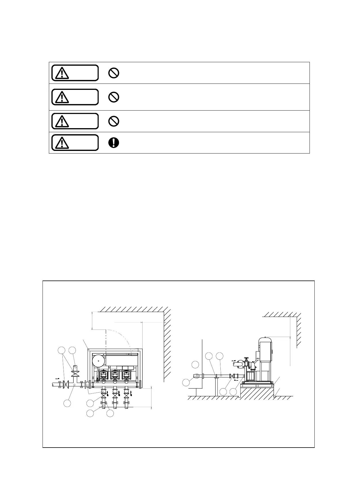
(1) Attach a companion flange c to the water supply unit after connecting the pipe.
(2) Install an adequate pipe support d so that the weight of the piping system will not be applied to the main
unit.
(3) For test operation and adjustments, be sure to attach sluice valves f and a test pipe g to the discharge
pipe e.
(4) Ensure to install a suction pipe h to each pump.
(5) The suction pipes h must be as short and straight as possible with minimal bends.
(6) To minimize the piping loss, the bore of the suction pipes h must be equal to or one size larger than that of
the pump. Pay special attention because the flow rate of the subsequently activated pump exceeds the
value devided the maximum water usage by the maximun number of paralleled units.
(7) For maintenance, be sure to attach sluice valves i to the suction pipes h.
(For negative suction type, do not attach sluice valves i to the suction pipes.)
(8) Ensure to attach strainers j to the ends of the suction pipes h in order to block the entrance of foreign
matter.
(9) After piping work, be sure to clean the inside of a receiver tank k to prevent the entry of foreign matter into
the pumps.
<Piping work example>
Maintenance space
600mm or more
Vibration isolation
frame base
(Special attachment)
Drainage
ditch
Receiver
tank
9
1
2
8
6
7
54
3
Vibration
isolation fitting
Drainage
ditch
7
6 2
Maintenance space
600mm or more
Maintenance space
600mm or more
Maintenance space
600mm or more
Note) Maintenance space indicates manufacturer’s
recommendations.
Fig. 4-2 Piping work example (for positive suction type)