10-2
10.2 Models with outdoor cover
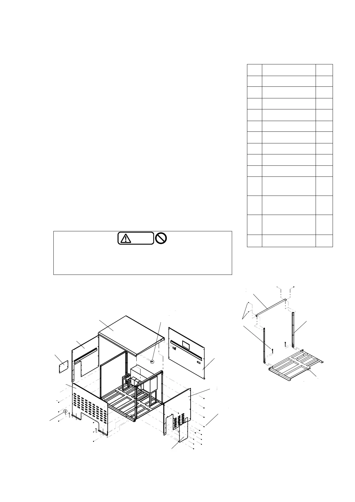
This section describes the assembly and disassembly of the outdoor cover.
Remove the outdoor cover before installation.
Also, remove the top plate and the front plate of the outdoor cover, before
operating the control panel.
(1)
Attach the mounting leg
ձ
to the unit base.
(Mounting screw
䐪
x 8pcs)
(2)
Attach the top plate support
䐠
to the mounting leg
䐟
.
(Mounting screw
䐪
x 8pcs)
(3) Attach the back plate
䐡
and front plate
䐢
to the mounting leg
䐟
.
(Decorative screw
䐨
x 16pcs)
(4) Attachl the left side plate
䐣
to the mounting leg
䐟
, and the side plate
lid
䐥
to the left side plate
䐣
.
(Decorative screw
䐨
x 16pcs)
(5)
Attach the right side plate
䐤
in the same manner as the left side plate
䐣
, and attach the discharge port lid
䐦
.
(Decorative screw
䐨
x12pcs)
* The discharge direction can be changed by exchanging the side plate
cover
䐥
and the discharge port cover
䐦
.
(6) Fix the back board
䐡
and the front board
䐢
to the unit base with the
mounting screws.
(Mounting screw
䐪
x 8pcs)
(7) Fit a hexagon bolt
䐫
on the top board
䐧
,
and attach it in alignment
with the notch of the top plate support
䐠
.
Next, fix the top board
䐧
and the top board support
䐠
with the
decorative screw
䐩
.
(Decorative screw
䐩
x4pcs, Hexagon bolt
䐫
x4pcs)
(8) When disassembling the outdoor cover, perform in the reverse order.
Caution
࣭Do not steop on the outside cover.
࣭Do not place any items on the outside cover.
࣭Do not remove the inspection window.
࣭Do not disassemble the outside cover in the wet weather.
No Accessory Qty
ձ
Mounting leg 4
ղ
Top plate support 2
ճ
Back plate 1
մ
Front plate 1
յ
Left side plate 1
ն
Right side plate 1
շ
Side plate lid 1
ո
Discharge port lid 1
չ
Top plate 1
պ
Decorative (Urea)
screw
ᲢNo.3 M6X10Უ
44
ջ
Decorative (Urea)
screw
ᲢNo.3 M6X21Უ
44
ռ
Mounting bolt
ᲢCross recessed
head tapping screw
Უ
24
ս
Hexagon bolt 4
Ĵټெ
İெ
IJெᔟ
ĮᏑெ
ijӻЈӝᔟ
ıӫெ
įЭெ
ĵ҄ታȍǸ
ĵ҄ታȍǸ
ķӕ˄ȍǸ
Ķ҄ታȍǸ
ĸρᚌȜȫȈ
Side
late lidSide
late lidSide
late lidSide
late lid
Decorative
Side
late lid
Hex. bolt
Left side
late
Top plate
Decorative
Mountin
scre
Right side
late
Discharge
ort lid
Back
late
Decorative
scre
The figure shows a representative model. The dimensions
may be partially different according to the model.
Front
late
Ĭӕ˄Ꮹ
ĭټெૅƑ
ȦȋȃȈșȸǹ
ķӕ˄ȍǸ
Top plate
su
ort
Mountin
le
Unit base
Moutin
bolt