7-7
(B)
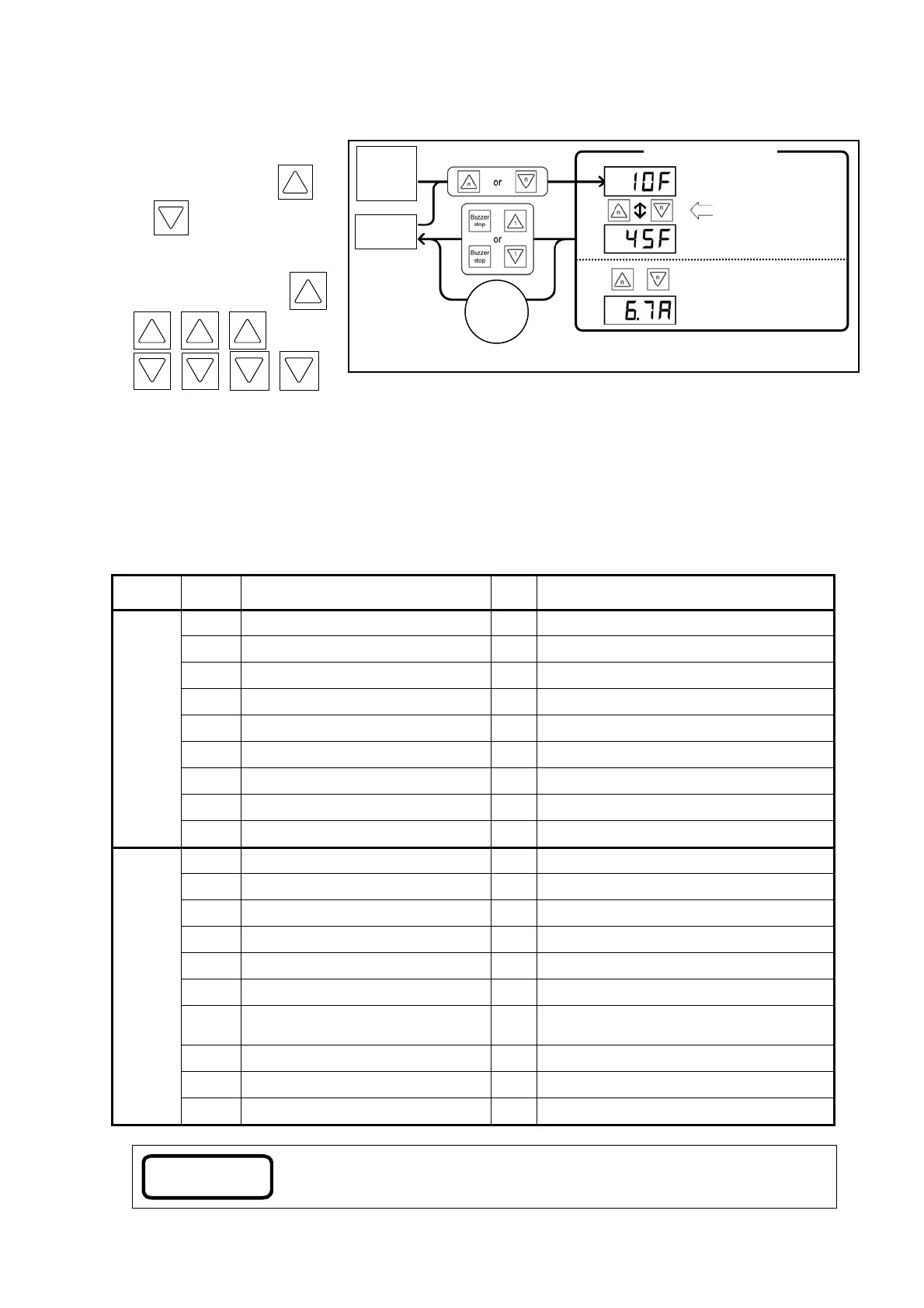
If
the operation mode is set to “Manual”:
When basic information is
displayed, press the
1
or
1
switch and the
Pump no.1 information is
displayed.
Similarly, press either
2
3 4 5
or
switch. Information for No.2 to 5 pumps is displayed.
The display returns to normal indication when no operation is carried out for 5 seconds or through the
Indication Switching Operation for basic information.
7.5 Parameter settings
Functions of the water supply unit can be configured and sdjusted using parameters.
Parameter settings are retained when the power is turned off.
7.5.1 Parameter list
Table 7-5-1 Parameter list
Class
Display
code
Parameter
Initial
value
Adjustable range
Basic
PH Total pump head 10
1 to 95 [m
䡡
H
2
O]
PL Min. sustained head 7
1 to PH [m
䡡
H
2
O]
1Go Permission for No. 1 run on
on : Permission for No. 1 run
off : Inhibition for No. 2 run
2Go Permission for No. 2 run on
on : Permission for No. 2 run
off : Inhibition for No. 2 run
3Go Permission for No. 3 run on
on : Permission for No. 3 run
off : Inhibition for No. 3 run
4Go Permission for No. 4 run on
on : Permission for No. 4 run
off : Inhibition for No. 4 run
5Go Permission for No. 5 run on
on : Permission for No. 5 run
off : Inhibition for No. 5 run
CHEC Inspection mode off
on : In inspection mode
off : In normal mode
ECO Energy-saving operation setting on
on : enables energy-saving operation
off : disables energy-saving operation
Extended
P100 External relay output pattern 0
0 to 4 :
Æ refer to 7.5.4 (1).
P101 Number of water level electrodes 4
4 : 4 poles
5 : 5 poles
P102 5P electrode pattern 0
0 : Standard
1 : Special
P103 Solenoid valve type 0
0 : Opened when power is turned on
1 : Closed when power is turned on
P104 Solenoid valve control system 0
0 : All together
1 : Alternately
P105 Interlock signal 0
0 : Contact “a”
1 : Contact “b
P200 Buzzer stop time 60
0 : No buzzer
1 to 60 :
Time until the buzzer stops [min.]
99
: No buzzer stop
P201 High-temperature alarm detection 1
0 : Not detected
1 : Detected
P202
Abnormal start frequency alarm detection
1
0 : Not detected
1 : Detected
P203 Water level alarm resetting method 0
0 : Manual
1 : Automatic
Note
The initial settings shown above are standard factory defaults.
If you specify a different value or option upon placing an order, the specified
value and option are preset in the parameter.
Preset frequency
e.g. 10 Hz
The long-press switch will
continuously increase or
decrease the preset frequency.
Preset frequency is changed
e.g. 45 Hz
Press both switches at the same time.
(This is displayed only when the
switches are held down during the
operation of the pump.)
e.
. 6.7 A
+
* The letter “n” indicates the corresponding pump number.
No
operation
for
5 seconds
Other pump
information
displayed
Fig. 7-4-3(B) Indications of pump information
#n Pump information
Normal
indication