Do you have a question about the Terasic Altera Cyclone V GX Starter Kit and is the answer not in the manual?
Lists the items included in the Cyclone V GX Starter Kit package.
Details the contents and availability of the starter kit's system CD.
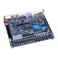
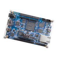
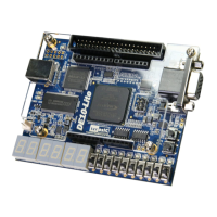
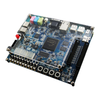
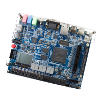
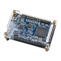
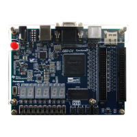
Describes the features and design characteristics of the development board.
Presents a block diagram illustrating the board's connections and functionality.
Provides contact information and resources for technical support.
Guides users through the installation and activation process for the Control Panel software.
Explains how to control the board's LEDs and 7-segment displays using the Control Panel.
Details how to monitor the status of slide switches and push-buttons on the board.
Describes how to read/write data to the SRAM and LPDDR2 memory chips.
Explains how to read the identification and specification information of an SD Card.
Guides users on viewing the readings from the board's analog-to-digital converter.
Details how to verify the UART to USB serial communication interface.
Explains the function for outputting color patterns to an HDMI display.
Describes how to verify the functionality of signals on the HSMC connector.
Explains the underlying architecture and operation of the C5G Control Panel.
Details methods for configuring the FPGA and understanding board status indicators.
Describes user interfaces like push-buttons, slide switches, LEDs, and 7-segment displays.
Explains the on-board clock generator and its frequencies.
Details the RS-232 to USB communication interface for board-to-PC connectivity.
Provides pin assignments and functions for the on-board SRAM.
Details pin assignments and functions for the LPDDR2 SDRAM.
Explains connections and functions for the Micro SD Card interface.
Details the pin assignments and functions of the HDMI Transmitter interface.
Describes the audio CODEC pin assignments and functions for audio input/output.
Explains the HSMC connector, its banks, power supply, and pin assignments.
Details the GPIO expansion header, its pin arrangement, and Arduino compatibility.
Introduces the C5G System Builder utility for creating custom design projects.
Outlines the general steps for building a project using the System Builder.
Provides detailed procedures for installing, launching, and using the C5G System Builder.
Describes the default configuration bit-stream demonstrating board features.
Presents a memory test function for the LPDDR2 SDRAM bank.
Demonstrates a memory test function for the board's SRAM.
Shows how to control LEDs by sending commands via UART-USB.
Introduces a reference design for the on-board ADV7513 HDMI encoder.
Demonstrates a project to test the XCVR HSMC Loopback function.
Shows how to implement an audio recorder and player using the C5G board.
Demonstrates how to browse files and read contents from an SD Card.
Implements an SD Card Music Player to play music files from an SD Card.
| FPGA | Altera Cyclone V GX |
|---|---|
| SRAM | 2 MB |
| Flash | 128MB |
| Ethernet | 10/100/1000 Mbps |
| USB | USB 2.0 |
| Power Supply | 12V DC |
| Connectors | Various |
| Clocking | 50 MHz |
| Expansion Headers | GPIO, HSMC |
| Operating Temperature | 85°C |