SM 1971 4-00
4
Centre Axle - Differential Drive Head
Section 150-0020
DISASSEMBLY
Numbers in parentheses refer to Fig. 1, unless
otherwise specified.
1. If not done so previously, remove bolts (50 & 74)
which attach countershaft case (49) to differential
housing (73) and lift off the countershaft case
assembly.
2. Remove cotter pins (66) and adjusting nuts (67).
Index mark bearing caps (62) and differential housing
(73). Remove lockwire (65), bolts (63), washers (64)
and bearing caps (62). Remove the outer races of
tapered bearings (68) from differential assembly (70).
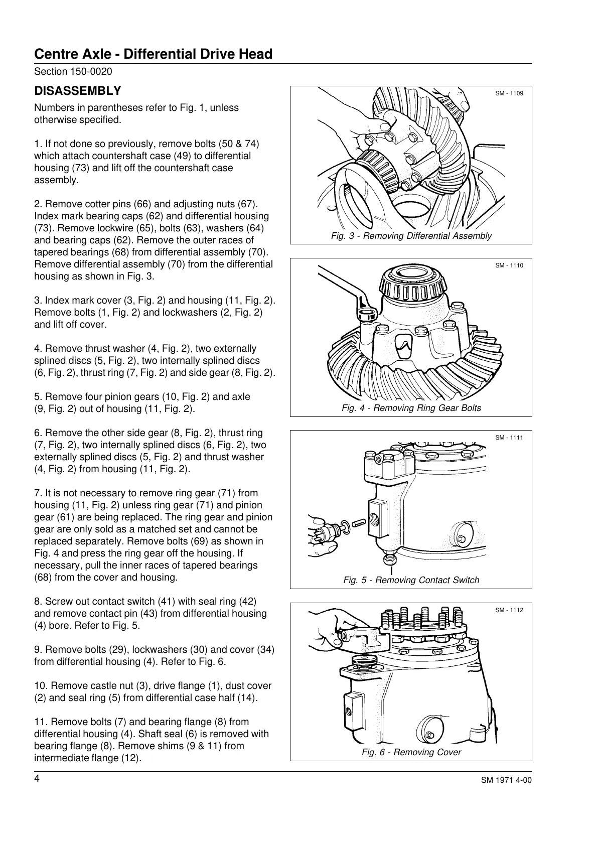
Remove differential assembly (70) from the differential
housing as shown in Fig. 3.
3. Index mark cover (3, Fig. 2) and housing (11, Fig. 2).
Remove bolts (1, Fig. 2) and lockwashers (2, Fig. 2)
and lift off cover.
4. Remove thrust washer (4, Fig. 2), two externally
splined discs (5, Fig. 2), two internally splined discs
(6, Fig. 2), thrust ring (7, Fig. 2) and side gear (8, Fig. 2).
5. Remove four pinion gears (10, Fig. 2) and axle
(9, Fig. 2) out of housing (11, Fig. 2).
6. Remove the other side gear (8, Fig. 2), thrust ring
(7, Fig. 2), two internally splined discs (6, Fig. 2), two
externally splined discs (5, Fig. 2) and thrust washer
(4, Fig. 2) from housing (11, Fig. 2).
7. It is not necessary to remove ring gear (71) from
housing (11, Fig. 2) unless ring gear (71) and pinion
gear (61) are being replaced. The ring gear and pinion
gear are only sold as a matched set and cannot be
replaced separately. Remove bolts (69) as shown in
Fig. 4 and press the ring gear off the housing. If
necessary, pull the inner races of tapered bearings
(68) from the cover and housing.
8. Screw out contact switch (41) with seal ring (42)
and remove contact pin (43) from differential housing
(4) bore. Refer to Fig. 5.
9. Remove bolts (29), lockwashers (30) and cover (34)
from differential housing (4). Refer to Fig. 6.
10. Remove castle nut (3), drive flange (1), dust cover
(2) and seal ring (5) from differential case half (14).
11. Remove bolts (7) and bearing flange (8) from
differential housing (4). Shaft seal (6) is removed with
bearing flange (8). Remove shims (9 & 11) from
intermediate flange (12).
SM - 1109
Fig. 3 - Removing Differential Assembly
Fig. 4 - Removing Ring Gear Bolts
SM - 1110
SM - 1111
Fig. 5 - Removing Contact Switch
SM - 1112
Fig. 6 - Removing Cover
Courtesy of Machine.Market


 To Next Page
 Loading...