1
SM 1480 9-98
Section 180-0021
SUSPENSION SYSTEM - Air Spring
DESCRIPTION
Numbers in parentheses refer to Fig. 1.
The air springs are hermetically sealed assemblies
which have flexible walls, no reciprocating parts and
no sliding seals. The air springs are virtually
frictionless in operation and maintenance free. Each
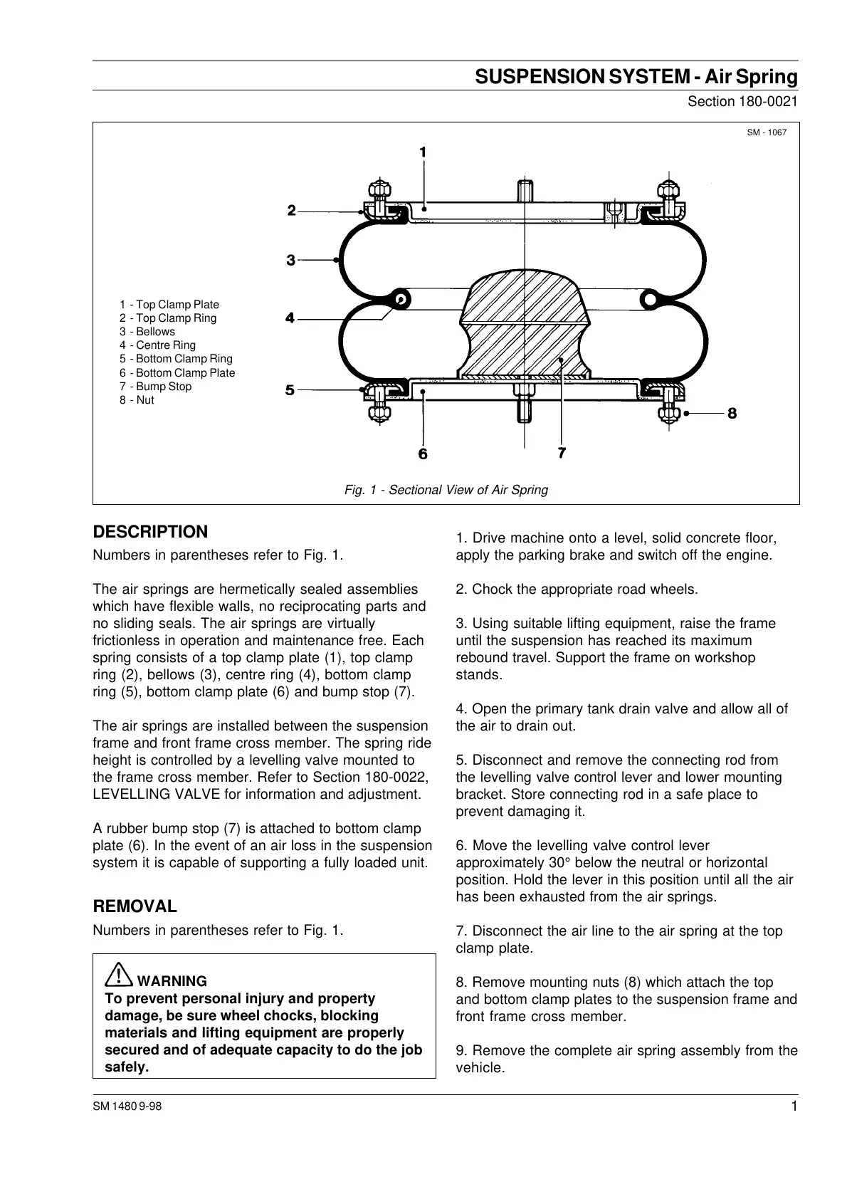
spring consists of a top clamp plate (1), top clamp
ring (2), bellows (3), centre ring (4), bottom clamp
ring (5), bottom clamp plate (6) and bump stop (7).
The air springs are installed between the suspension
frame and front frame cross member. The spring ride
height is controlled by a levelling valve mounted to
the frame cross member. Refer to Section 180-0022,
LEVELLING VALVE for information and adjustment.
A rubber bump stop (7) is attached to bottom clamp
plate (6). In the event of an air loss in the suspension
system it is capable of supporting a fully loaded unit.
REMOVAL
Numbers in parentheses refer to Fig. 1.
WARNING
To prevent personal injury and property
damage, be sure wheel chocks, blocking
materials and lifting equipment are properly
secured and of adequate capacity to do the job
safely.
1. Drive machine onto a level, solid concrete floor,
apply the parking brake and switch off the engine.
2. Chock the appropriate road wheels.
3. Using suitable lifting equipment, raise the frame
until the suspension has reached its maximum
rebound travel. Support the frame on workshop
stands.
4. Open the primary tank drain valve and allow all of
the air to drain out.
5. Disconnect and remove the connecting rod from
the levelling valve control lever and lower mounting
bracket. Store connecting rod in a safe place to
prevent damaging it.
6. Move the levelling valve control lever
approximately 30° below the neutral or horizontal
position. Hold the lever in this position until all the air
has been exhausted from the air springs.
7. Disconnect the air line to the air spring at the top
clamp plate.
8. Remove mounting nuts (8) which attach the top
and bottom clamp plates to the suspension frame and
front frame cross member.
9. Remove the complete air spring assembly from the
vehicle.
Fig. 1 - Sectional View of Air Spring
SM - 1067
1 - Top Clamp Plate
2 - Top Clamp Ring
3 - Bellows
4 - Centre Ring
5 - Bottom Clamp Ring
6 - Bottom Clamp Plate
7 - Bump Stop
8 - Nut
Courtesy of Machine.Market
 Loading...


