2
SM 1480 9-98
Section 180-0021
Suspension System - Air Spring
DISASSEMBLY
Numbers in parentheses refer to Fig. 2.
1. Remove top and bottom clamp plates (4 & 3) and
clamp rings (2) from bellows (1).
2. Remove centre ring (5) from bellows (1)
convolutions.
3. If necessary, remove nut (7) and bump stop (6)
from bottom clamp plate (3). A sealing compound is
applied to bump stop mounting face at assembly, it is
necessary to break the seal to remove bump stop.
INSPECTION
Numbers in parentheses refer to Fig. 2.
1. Clean clamp rings (2), bottom clamp plate (3), top
clamp plate (4) and centre ring (5) in solvent to
remove all contamination. Thoroughly dry all parts.
2. Inspect all parts for damage and excessive
corrosion. Replace all worn or damaged parts.
ASSEMBLY
Numbers in parentheses refer to Fig. 2.
1. If bump stop (6) was removed from bottom clamp
plate (3), coat the bump stop mounting face with
sealing compound, such as 'Heldite' or equivalent.
Bolt the bump stop to the lower clamp plate with
nut (7). Torque tighten nut (7) to 23 Nm (17 lbf ft).
2. Install centre ring (5) on bellows (1).
3. Lightly coat the top and bottom beads of the
bellows (1) with silicon or soapy water to aid in
assembly of clamp rings (2) and clamp plates
(3 & 4).
4. Install clamp rings (2) and bottom and top clamp
plates (3 & 4) on bellows (1).
INSTALLATION
Numbers in parentheses refer to Fig. 1.
WARNING
To prevent personal injury and property
damage, be sure wheel chocks, blocking
materials and lifting equipment are properly
secured and of adequate capacity to do the job
safely.
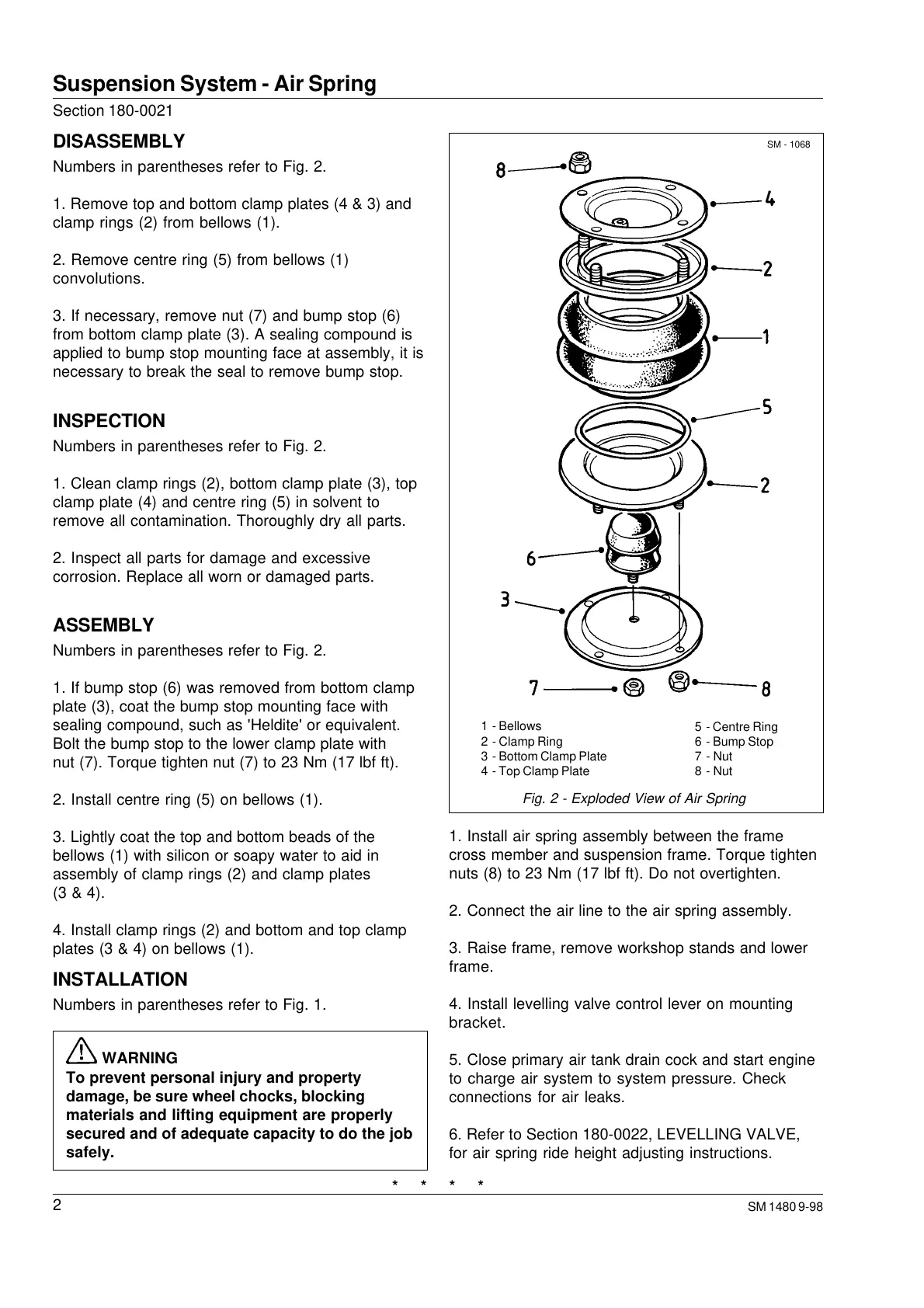
Fig. 2 - Exploded View of Air Spring
* * * *
1. Install air spring assembly between the frame
cross member and suspension frame. Torque tighten
nuts (8) to 23 Nm (17 lbf ft). Do not overtighten.
2. Connect the air line to the air spring assembly.
3. Raise frame, remove workshop stands and lower
frame.
4. Install levelling valve control lever on mounting
bracket.
5. Close primary air tank drain cock and start engine
to charge air system to system pressure. Check
connections for air leaks.
6. Refer to Section 180-0022, LEVELLING VALVE,
for air spring ride height adjusting instructions.
SM - 1068
1 - Bellows
2 - Clamp Ring
3 - Bottom Clamp Plate
4 - Top Clamp Plate
5 - Centre Ring
6 - Bump Stop
7 - Nut
8 - Nut
Courtesy of Machine.Market
 Loading...


