Body System - Body Cylinder
SM 1956 4-00
Section 230-0130
4
3. Install spacers (25) in rod end of cylinder, align
spherical bearing with bores in body and install upper
pin (24) through mounting bores, spacers (25) and
cylinder. Secure upper pin (24) with washer (28),
lockwasher (27) and bolt (26). Tighten bolt (26) to a
torque of 66 Nm (49 lbf ft).
4. Connect the hydraulic oil lines to the cylinder ports
as tagged during removal.
5. Lubricate pins at lube fittings (22) with lubricant as
specified in Section 300-0020, LUBRICATION SYSTEM.
6. Check oil level in hydraulic tank and add if low.
Refer to Section 230-0040, HYDRAULIC TANK, for
correct fill level. Refer to Section 300-0020,
LUBRICATION SYSTEM, for the type of oil used.
7. Place the battery master switch in the 'On' position,
start the engine, operate the body and check cylinder lines
for leaks. Tighten lines and fittings as required.
8. Remove wheel blocks from road wheels.
MAINTENANCE
Every 50 hours: Lubricate cylinder pins as described
in Section 300-0020, LUBRICATION SYSTEM. Inspect
cylinders for leaks, if leaks are found, replace seals
with seals contained in the Service Repair Kit, as
specified in the parts book.
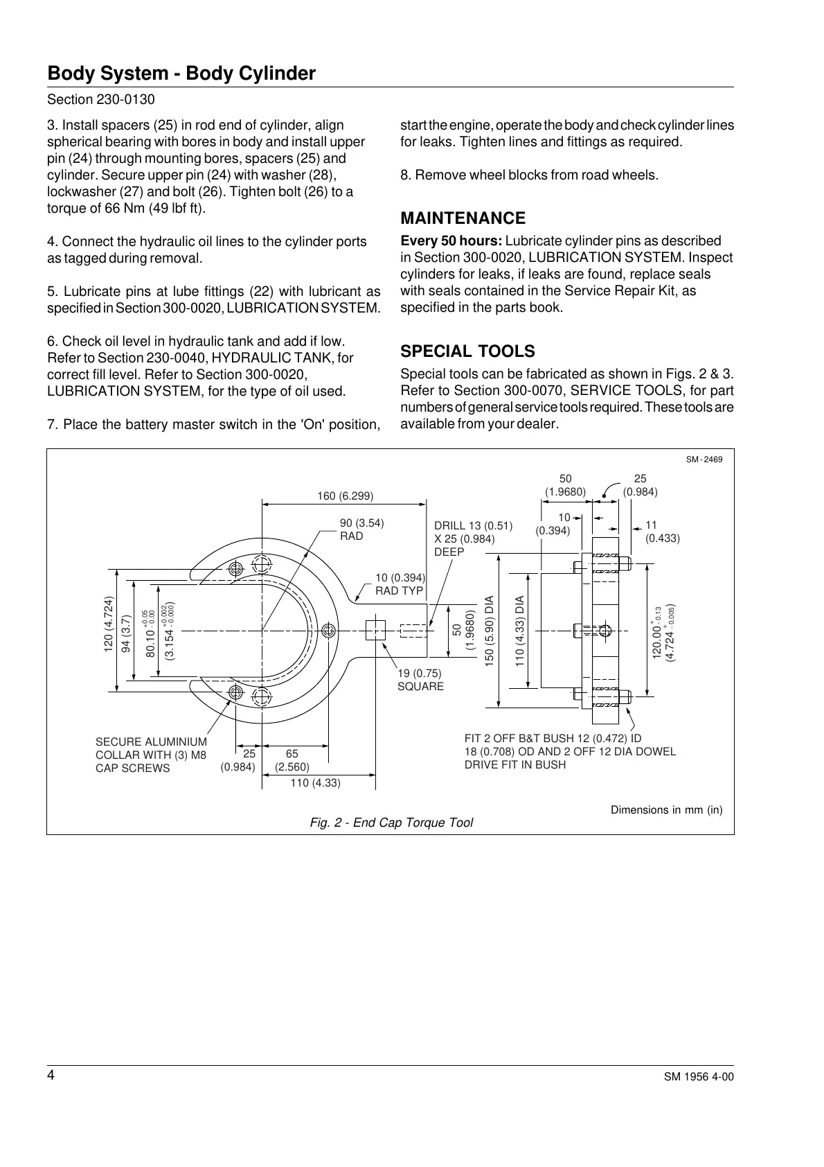
SPECIAL TOOLS
Special tools can be fabricated as shown in Figs. 2 & 3.
Refer to Section 300-0070, SERVICE TOOLS, for part
numbers of general service tools required. These tools are
available from your dealer.
SM - 2469
Fig. 2 - End Cap Torque Tool
Dimensions in mm (in)
160 (6.299)
150 (5.90) DIA
110 (4.33) DIA
120 (4.724)
94 (3.7)
90 (3.54)
RAD
10 (0.394)
RAD TYP
19 (0.75)
SQUARE
25
(0.984)
10
(0.394)
11
(0.433)
65
(2.560)
50
(1.9680)
50
(1.9680)
25
(0.984)
110 (4.33)
80.10
+0.05
- 0.00
(3.154 )
+0.002
- 0.000
120.00
+
- 0.13
(4.724 )
+
- 0.005
SECURE ALUMINIUM
COLLAR WITH (3) M8
CAP SCREWS
DRILL 13 (0.51)
X 25 (0.984)
DEEP
FIT 2 OFF B&T BUSH 12 (0.472) ID
18 (0.708) OD AND 2 OFF 12 DIA DOWEL
DRIVE FIT IN BUSH
Courtesy of Machine.Market
 Loading...


