1
Section 250-0200
SM 1985 Rev 1 11-00
BRAKING SYSTEM - Air Drier
SM - 1942
DESCRIPTION
Numbers in parentheses refer to Fig. 1.
The air drier is mounted on the left hand side platform,
with the purge tank located inboard of the hood
assembly, mounted off the right hand side of the
goalpost support assembly.
The purpose of the air drier is to filter the air from the
compressor to remove any oil and moisture before it
enters the air reservoirs.
Note: An air system maintained to proper specification
can lead to prolonged component life. It is important
therefore to follow the servicing procedures contained
in this section.
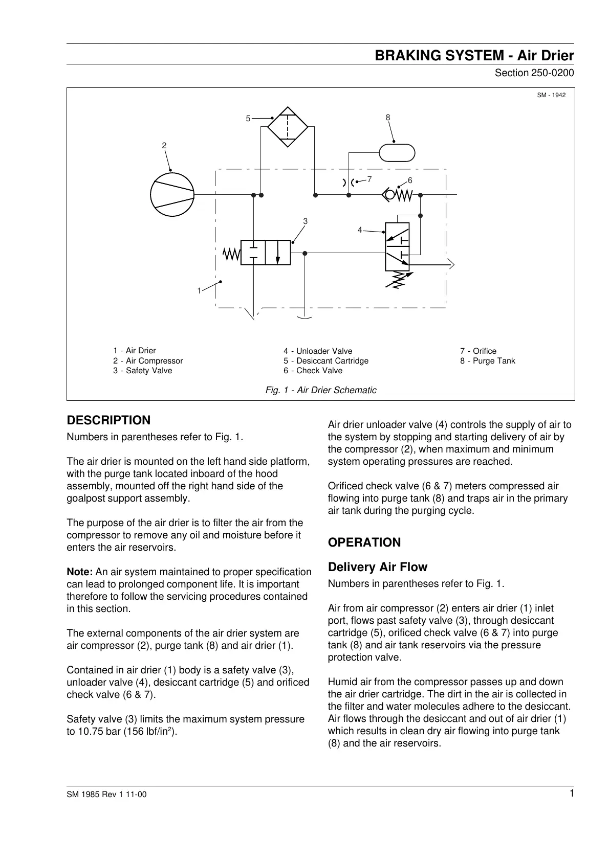
The external components of the air drier system are
air compressor (2), purge tank (8) and air drier (1).
Contained in air drier (1) body is a safety valve (3),
unloader valve (4), desiccant cartridge (5) and orificed
check valve (6 & 7).
Safety valve (3) limits the maximum system pressure
to 10.75 bar (156 lbf/in
2
).
Air drier unloader valve (4) controls the supply of air to
the system by stopping and starting delivery of air by
the compressor (2), when maximum and minimum
system operating pressures are reached.
Orificed check valve (6 & 7) meters compressed air
flowing into purge tank (8) and traps air in the primary
air tank during the purging cycle.
OPERATION
Delivery Air Flow
Numbers in parentheses refer to Fig. 1.
Air from air compressor (2) enters air drier (1) inlet
port, flows past safety valve (3), through desiccant
cartridge (5), orificed check valve (6 & 7) into purge
tank (8) and air tank reservoirs via the pressure
protection valve.
Humid air from the compressor passes up and down
the air drier cartridge. The dirt in the air is collected in
the filter and water molecules adhere to the desiccant.
Air flows through the desiccant and out of air drier (1)
which results in clean dry air flowing into purge tank
(8) and the air reservoirs.
7 - Orifice
8 - Purge Tank
4 - Unloader Valve
5 - Desiccant Cartridge
6 - Check Valve
1 - Air Drier
2 - Air Compressor
3 - Safety Valve
Fig. 1 - Air Drier Schematic
5
2
1
3
4
6
7
8
Courtesy of Machine.Market
 Loading...


