2
Braking System - Air Drier
Section 250-0200
SM 1985 Rev 1 11-00
Purging Air Flow
Numbers in parentheses refer to Fig. 1.
When system pressure reaches 8.4 bar (122 lbf/in²),
the air pressure overcomes spring tension in purge
valve which forces the spool down. This unloads air
compressor (2) by opening unloader valve (4) and
allowing the air to flow out of purge tank (8), through
orifice (7), unloader valve (4) and air drier (1) drain to
atmosphere.
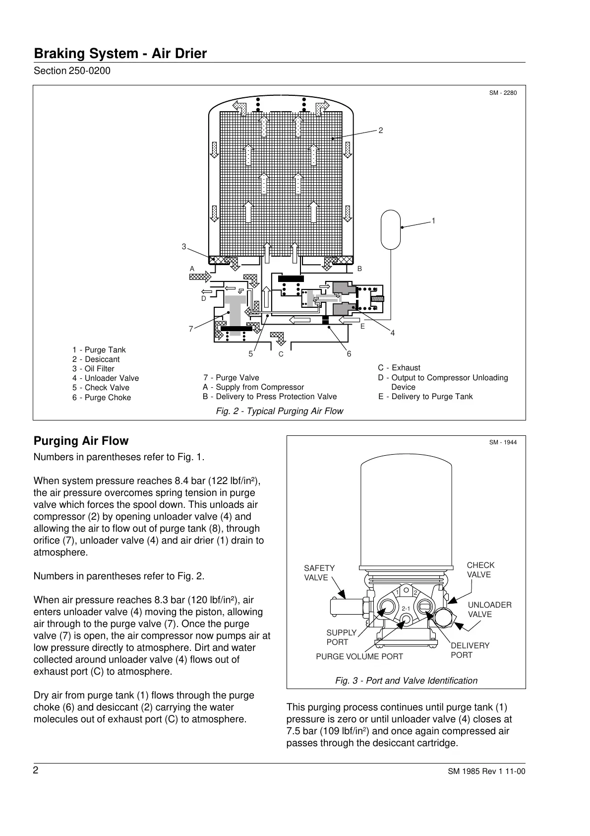
Numbers in parentheses refer to Fig. 2.
When air pressure reaches 8.3 bar (120 lbf/in²), air
enters unloader valve (4) moving the piston, allowing
air through to the purge valve (7). Once the purge
valve (7) is open, the air compressor now pumps air at
low pressure directly to atmosphere. Dirt and water
collected around unloader valve (4) flows out of
exhaust port (C) to atmosphere.
Dry air from purge tank (1) flows through the purge
choke (6) and desiccant (2) carrying the water
molecules out of exhaust port (C) to atmosphere.
SM - 2280
Fig. 2 - Typical Purging Air Flow
C - Exhaust
D - Output to Compressor Unloading
Device
E - Delivery to Purge Tank
7 - Purge Valve
A - Supply from Compressor
B - Delivery to Press Protection Valve
1 - Purge Tank
2 - Desiccant
3 - Oil Filter
4 - Unloader Valve
5 - Check Valve
6 - Purge Choke
SM - 1944
Fig. 3 - Port and Valve Identification
This purging process continues until purge tank (1)
pressure is zero or until unloader valve (4) closes at
7.5 bar (109 lbf/in
2
) and once again compressed air
passes through the desiccant cartridge.
CHECK
VALVE
UNLOADER
VALVE
SAFETY
VALVE
DELIVERY
PORT
SUPPLY
PORT
PURGE VOLUME PORT
1
2
2-1
2
1
4
56
7
3
AB
D
C
E
Courtesy of Machine.Market
 Loading...


