3
Section 250-0200
SM 1985 Rev 1 11-00
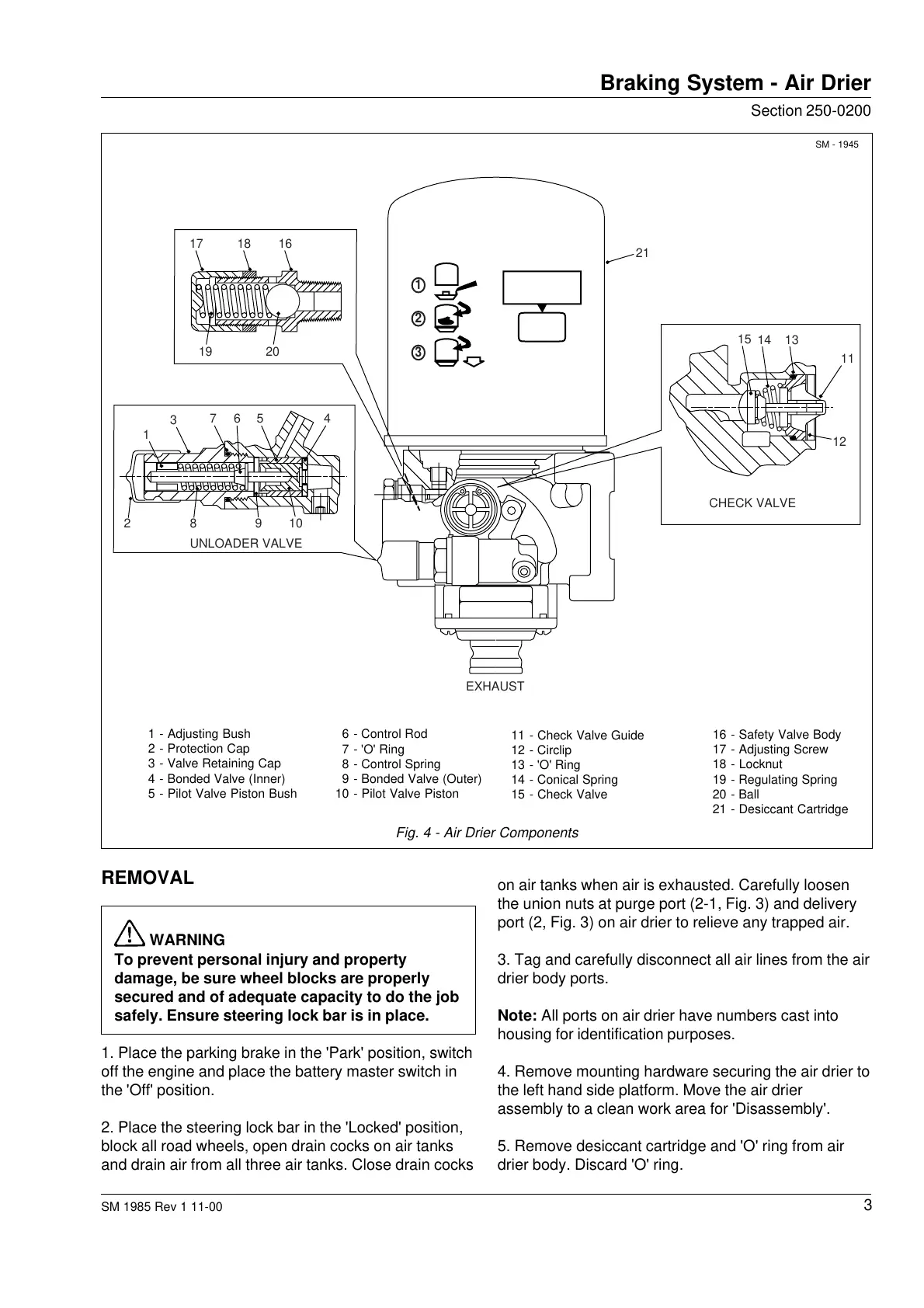
Fig. 4 - Air Drier Components
11 - Check Valve Guide
12 - Circlip
13 - 'O' Ring
14 - Conical Spring
15 - Check Valve
6 - Control Rod
7 - 'O' Ring
8 - Control Spring
9 - Bonded Valve (Outer)
10 - Pilot Valve Piston
1 - Adjusting Bush
2 - Protection Cap
3 - Valve Retaining Cap
4 - Bonded Valve (Inner)
5 - Pilot Valve Piston Bush
REMOVAL
WARNING
To prevent personal injury and property
damage, be sure wheel blocks are properly
secured and of adequate capacity to do the job
safely. Ensure steering lock bar is in place.
1. Place the parking brake in the 'Park' position, switch
off the engine and place the battery master switch in
the 'Off' position.
2. Place the steering lock bar in the 'Locked' position,
block all road wheels, open drain cocks on air tanks
and drain air from all three air tanks. Close drain cocks
on air tanks when air is exhausted. Carefully loosen
the union nuts at purge port (2-1, Fig. 3) and delivery
port (2, Fig. 3) on air drier to relieve any trapped air.
3. Tag and carefully disconnect all air lines from the air
drier body ports.
Note: All ports on air drier have numbers cast into
housing for identification purposes.
4. Remove mounting hardware securing the air drier to
the left hand side platform. Move the air drier
assembly to a clean work area for 'Disassembly'.
5. Remove desiccant cartridge and 'O' ring from air
drier body. Discard 'O' ring.
Braking System - Air Drier
SM - 1945
16 - Safety Valve Body
17 - Adjusting Screw
18 - Locknut
19 - Regulating Spring
20 - Ball
21 - Desiccant Cartridge
1
2
3
28910
11
21
1
3
7 5 46
2019
17 18 16
12
15
14 13
UNLOADER VALVE
CHECK VALVE
EXHAUST
Courtesy of Machine.Market
 Loading...


