Section 100-0020
7
SM 1988 Rev 1 11-00
Chassis - Articulation and Oscillation Pivot
and use lifting equipment to pull the rear frame away
from the front frame. After moving, block the rear
frame and wheels securely.
12. Mark all bearing retainers (5, 11, 17 & 21) to aid in
'Installation'.
Note: Retainers (5, 11, 17 & 21) are not
interchangeable.
13. Remove bolts (13), lockwashers (14), retainers
(5, 11, 17 & 21) and upper and lower shims (7, 8 & 9).
14. Remove and discard 'O' rings (4, 10 & 18).
Remove spacer (52) noting orientation to aid in
'Installation'.
15. Remove and tag all bearings (6) to aid in
'Installation', where appropriate.
Note: Never interchange cups or cones between
bearings.
Inspection
Numbers in parentheses refer to Fig. 1.
1. Clean parts with a suitable solvent and let dry. DO
NOT spin bearings with compressed air. Place
bearings on clean surface, cover with lint free cloth
and allow to dry.
2. Check articulation bearings (6) and pins (32 & 55)
for wear or damage. Renew if required.
Installation
Numbers in parentheses refer to Fig. 1, unless
otherwise specified.
WARNING
To prevent personal injury and property
damage, make sure blocking or lifting
equipment is properly secured and of adequate
capacity to do the job safely.
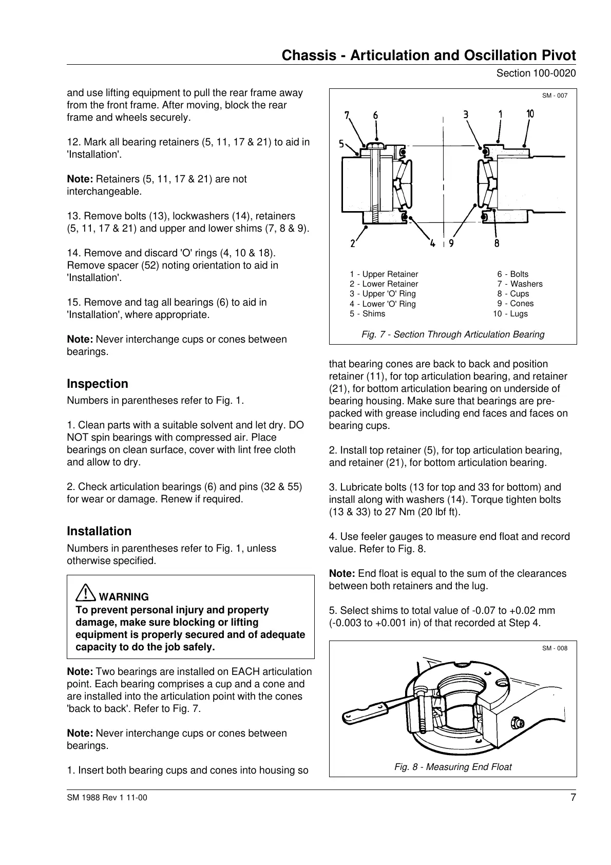
Note: Two bearings are installed on EACH articulation
point. Each bearing comprises a cup and a cone and
are installed into the articulation point with the cones
'back to back'. Refer to Fig. 7.
Note: Never interchange cups or cones between
bearings.
1. Insert both bearing cups and cones into housing so
SM - 007
Fig. 8 - Measuring End Float
that bearing cones are back to back and position
retainer (11), for top articulation bearing, and retainer
(21), for bottom articulation bearing on underside of
bearing housing. Make sure that bearings are pre-
packed with grease including end faces and faces on
bearing cups.
2. Install top retainer (5), for top articulation bearing,
and retainer (21), for bottom articulation bearing.
3. Lubricate bolts (13 for top and 33 for bottom) and
install along with washers (14). Torque tighten bolts
(13 & 33) to 27 Nm (20 lbf ft).
4. Use feeler gauges to measure end float and record
value. Refer to Fig. 8.
Note:
End float is equal to the sum of the clearances
between both retainers and the lug.
5. Select shims to total value of -0.07 to +0.02 mm
(-0.003 to +0.001 in) of that recorded at Step 4.
1 - Upper Retainer
2 - Lower Retainer
3 - Upper 'O' Ring
4 - Lower 'O' Ring
5 - Shims
6 - Bolts
7 - Washers
8 - Cups
9 - Cones
10 - Lugs
Fig. 7 - Section Through Articulation Bearing
SM - 008
Courtesy of Machine.Market


 To Next Page
 Loading...