Section 120-0010
1
SM 1965 4-00
23 - Screw
24 - Gasket
25 - Dipstick
26 - Latch Assembly
27 - Clamp
28 - Bolt
29 - Locknut
30 - Padlock
15 - Dipstick Tube
16 - Bracket
17 - Clamp
18 - Bolt
19 - Washer
20 - Locknut
21 - Bolt
22 - Lockwasher
8 - Isolation Mount
9 - Lockwasher
10 - Bolt
11 - Lockwasher
12 - Bolt
13 - RH Bracket
14 - Hardened Washer
1 - Front Bracket Assembly
2 - Isolation Mount
3 - Snubbing Washer
4 - Washer
5 - Locknut
6 - Bolt
7 - LH Bracket
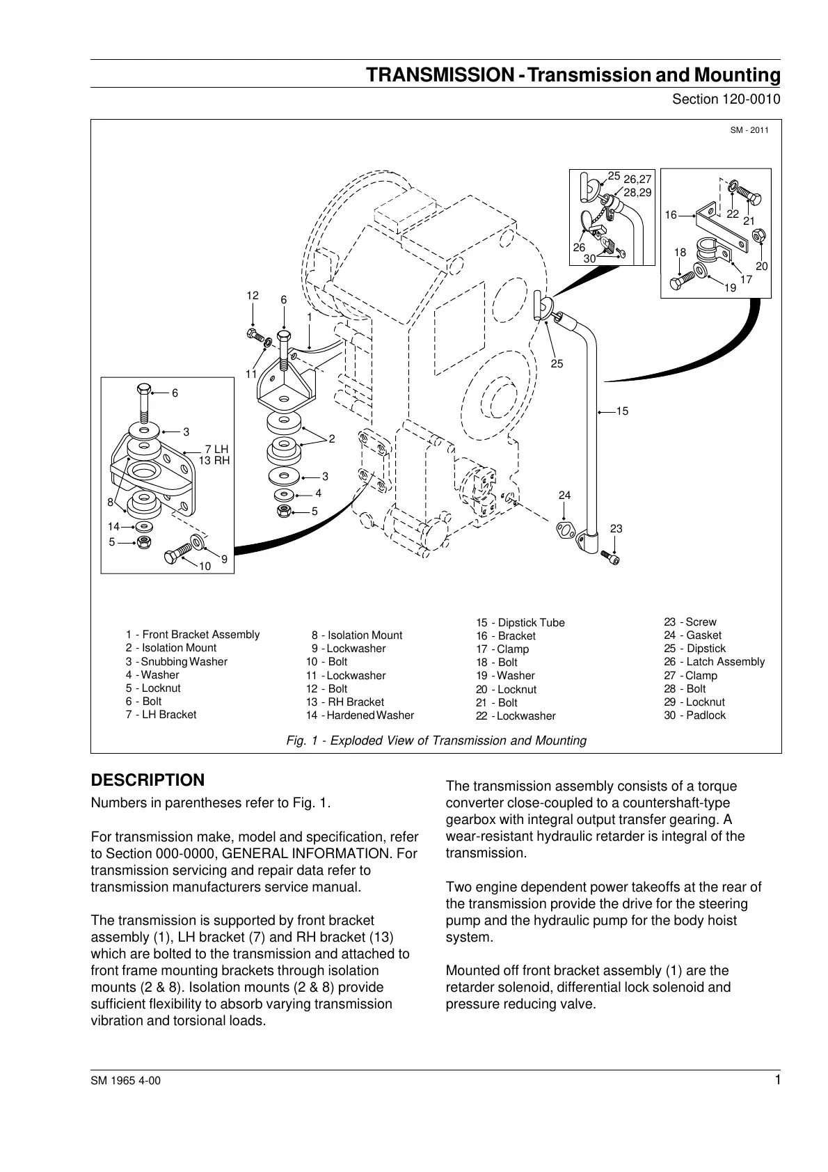
Fig. 1 - Exploded View of Transmission and Mounting
DESCRIPTION
Numbers in parentheses refer to Fig. 1.
For transmission make, model and specification, refer
to Section 000-0000, GENERAL INFORMATION. For
transmission servicing and repair data refer to
transmission manufacturers service manual.
The transmission is supported by front bracket
assembly (1), LH bracket (7) and RH bracket (13)
which are bolted to the transmission and attached to
front frame mounting brackets through isolation
mounts (2 & 8). Isolation mounts (2 & 8) provide
sufficient flexibility to absorb varying transmission
vibration and torsional loads.
The transmission assembly consists of a torque
converter close-coupled to a countershaft-type
gearbox with integral output transfer gearing. A
wear-resistant hydraulic retarder is integral of the
transmission.
Two engine dependent power takeoffs at the rear of
the transmission provide the drive for the steering
pump and the hydraulic pump for the body hoist
system.
Mounted off front bracket assembly (1) are the
retarder solenoid, differential lock solenoid and
pressure reducing valve.
TRANSMISSION - Transmission and Mounting
SM - 2011
2
1
3
4
5
11
12
6
6
7 LH
8
9
3
13 RH
10
14
5
24
23
15
25
18
19
17
16
22
21
20
25
30
26
26,27
28,29
Courtesy of Machine.Market